


14
• Turn mower on its side making sure that the air filter
and the carburetor are up.
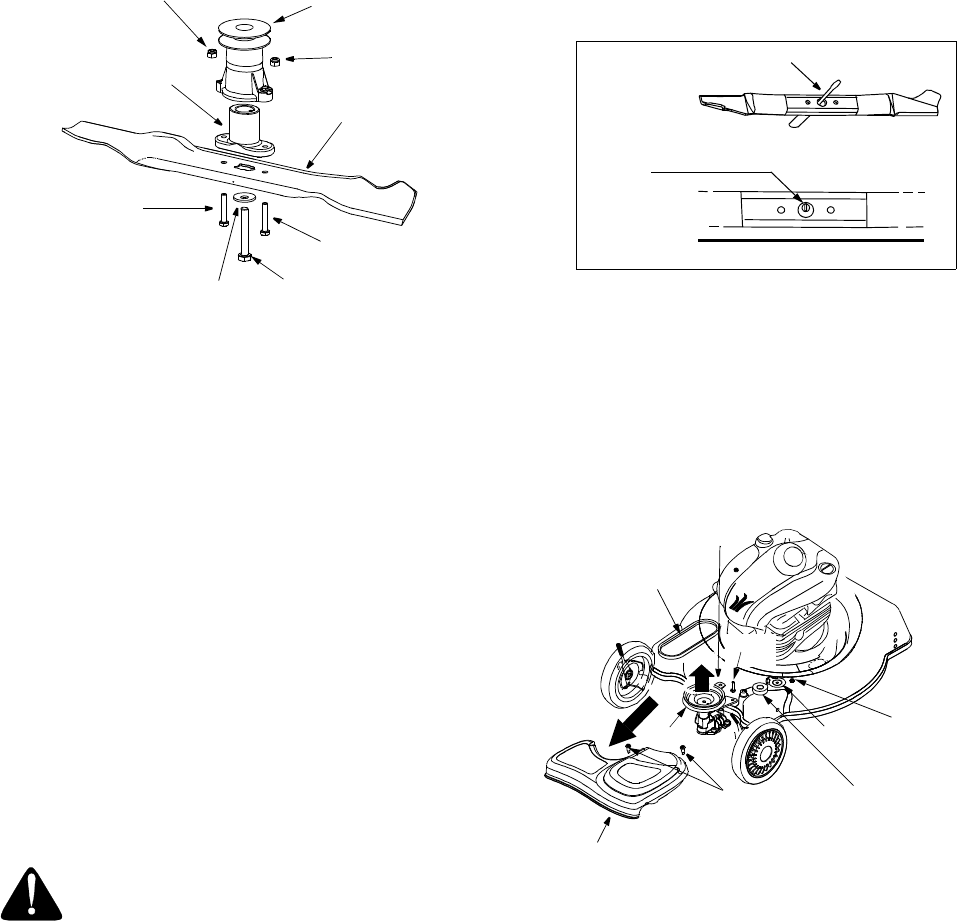
Figure 16
• Also lubricate the bolt holes, bolt and the inner
surface of the nuts.
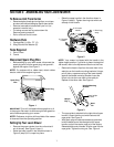
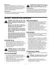
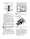
• Install the blade adapter on the pulley with the “star”
away from the pulley. See Figure 16.
• Place the new blade on the blade adapter with the
side marked bottom (or with part number) facing
away from the adapter.
• Secure the blade to the assembly with two hex
bolts and lock nuts. Tighten the hex bolts to the
recommended torque. Refer to ‘Blade Mounting
Torque’ section on this page.
• Install the blade assembly on the crankshaft. See
Figure 16. Secure with the hex bolt and bell washer
(cupped side of washer to blade) and tighten to the
recommended torque. Refer to ‘Blade Mounting
Torque’ section on this page.
IMPORTANT:
The bolt, used to secure the blade to the
engine, is specially heat-treated. Do not substitute. To
order replacement bolt, refer to the parts list in the back
of this manual.
WARNING: To ensure safe operation of
your lawn mower, check all nuts and bolts
periodically and tighten if necessary.
To Sharpen Blade:
• The blade can be sharpened with a file or on a
grinding wheel. Do not attempt to sharpen the
blade while it is still on the mower.
• Follow the original angle of grind as a guide. Make
sure that each cutting edge receives an equal
amount of grinding to prevent an unbalanced blade.
NOTE: An unbalanced blade will cause excessive
vibration when rotating at high speeds, may cause
damage to the mower and could break, causing
personal injury.
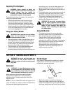
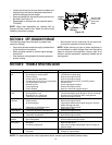
• The blade can be tested by balancing it on a round
shaft screwdriver. See Figure 17. Remove metal
from the heavy side until it balances evenly. It is
recommended that the blade always be removed
from the adapter for the best test of balance.
Figure 17
Blade Mounting Torque:
Blade adapter bolts: 120 in.lbs. minimum, 150 in.lbs.
maximum.
Center bolt: 450 in.lbs. minimum, 600 in.lbs. maximum.
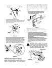
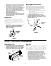
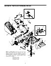
Replacing Drive Belt
Figure 18
• Remove the two shoulder screws which secure the
front drive cover to the mower deck. See Figure 18.
• Remove the front drive cover from the unit by lightly
pressing inward on the sides of the front drive
cover. This will release the tabs that secure the
front drive cover to the height adjuster brackets.
• Remove the idler from the idler bracket using 7/16”
wrench and socket. See Figure 18.
• Remove the belt from the transmission pulley as
shown in Figure 18.
• Lift and stabilize the front of the deck.
Lock Nut
Lock Nut
Pulley
Assembly
Blade
Adapter
Blade
Bell
Washer
Hex Bolt
Hex Bolt
Hex Bolt
1. Insert screw driver through hole
2. Blade should be parallel to ground
Screw
Driver
Ground
Blade
Lock Nut
Belt
Keeper
Idler
Idler
Bracket
Drive
Pulley
Front Drive
Shoulder
Screw
Cover
Belt
Bolt
The wheels have been moved forward in this picture for clarity.
Do
not remove
the wheels away from the mower housing while
performing the job.