


8
Section 2: Assembly
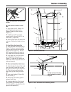
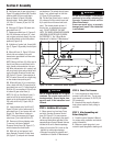
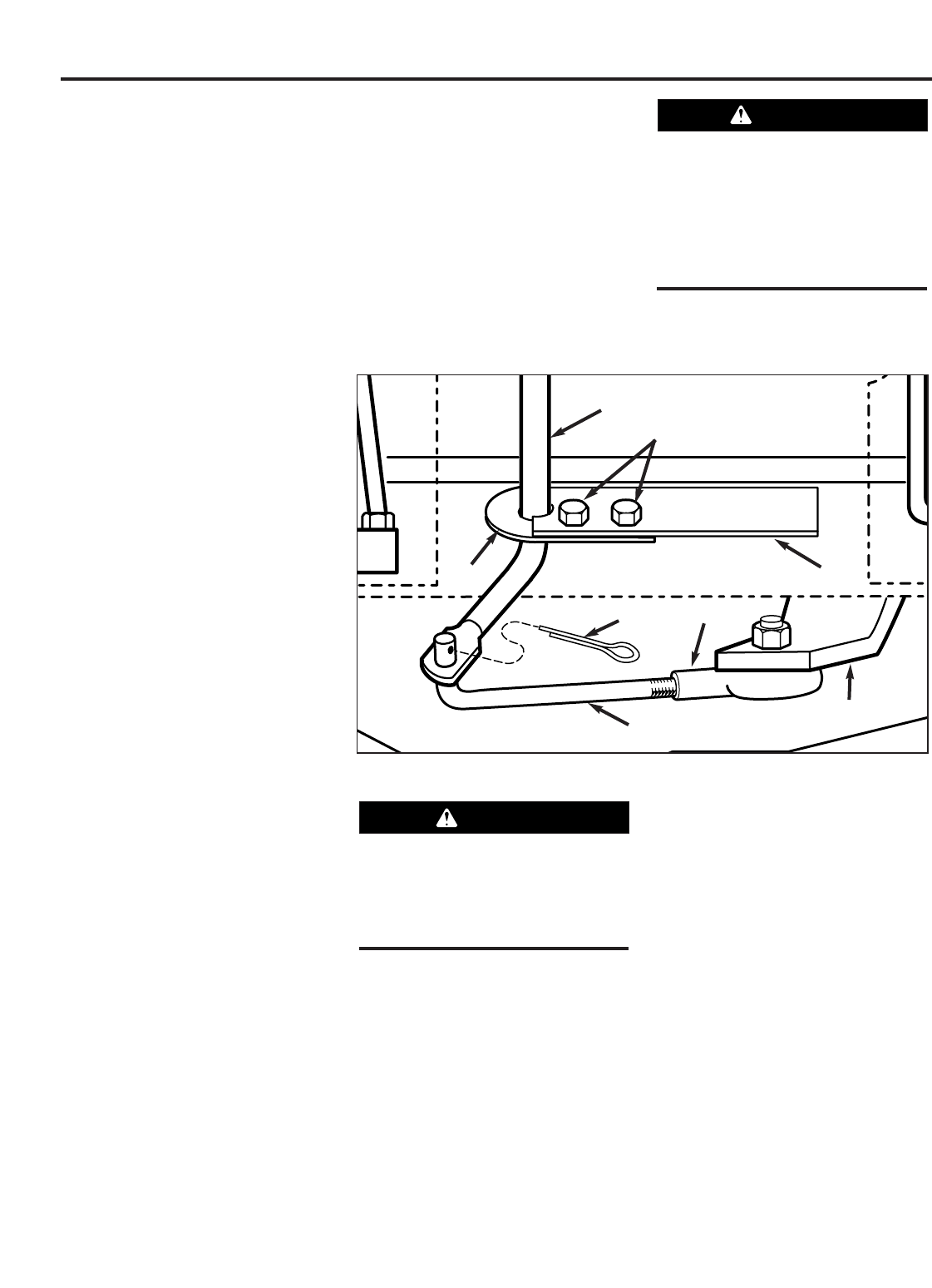
5. Hold lower part of gear select lever (I,
Figure 2-9) against bracket (M). Position
retaining plate (N) from parts bag in
place as shown in Figure 2-9 (plate
below bracket). Secure plate with two
1/4"-20 x 1/2" screws (O) and 1/4”-20
locknuts.
6. Slide grip (B, Figure 2-8) back onto
gear select lever (I).
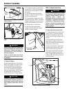
7. Rotate gear select lever (I, Figures 2-
8 & 2-9) clockwise until spur (K - short
rod) on gear select rod stops in the neu-
tral position detent on the shift pattern
quadrant (Figure 2-8).
8. At bottom of control rod, thread shift
link (P, Figure 2-9) partially into ball-joint
(Y).
9. Move shift arm (X, Figure 2-9) from
side to side as necessary into each
transmission gear detent until transmis-
sion is in neutral.
NOTE: Moving shift arm (X) all the way to
the left, and then one notch back to the
right, should put transmission into neu-
tral. When transmission is in neutral, unit
will move freely when pushed while hold-
ing the Operator Presence Control lever
(W, Figure 2-7) down. If transmission is
NOT in neutral, there will be a slight drag
on the wheels when pushing unit.
10. When shift arm (X) is in neutral po-
sition, rotate shift link (P) toward end of
gear select lever rod (I). Adjust length of
shift link (P) as necessary to fit into hole
in bottom of gear select lever (I).
NOTE: Pin (K) on Gear Select Lever (I)
must be held in the neutral position
detent on the shift quadrant (see Figure
2-8) while shift link (P, Figure 2-9) is
adjusted.
11. Insert hooked end of shift link (P,
Figure 2-9) into hole in bottom end of
gear select lever (I) and secure with cot-
ter pin (Q). Bend ends of cotter pin.
NOTE: It may be necessary to lift gear
select lever (I) to install shift link (P).
12. Remove unit from shipping crate.
To remove, hold down Operator
Presence Control lever (W, Figure 2-7)
which releases the wheel brake.
13. With unit on level ground, hold
down Operator Presence Control lever
(W, Figure 2-7) and push unit forward
and backward. The wheels should move
freely. If not, adjust length of shift link
(P, Figure 2-9) as necessary.
14. Put the Gear Select Lever in neutral
(N), release all of the control levers and
try to push the unit forward and back-
ward. The wheels should not turn. If
they do turn, an adjustment is neces-
sary. DO NOT OPERATE THE UNIT
UNTIL THE WHEEL BRAKE MECHANISM
HAS BEEN ADJUSTED AND IS WORK-
ING PROPERLY. See “Wheel Brake
Adjustment” in Section 5 “Maintenance.”
STEP 5: Add Motor Oil to Engine
1. Move mower to a level area. Press
and hold Operator Presence Control
lever (W, Figure 2-7) to move mower.
2. Add motor oil according to the specifi-
cations and instructions provided in the
separate Engine Owner’s Manual that was
included in the unit’s literature package.
• Keep oil level at the FULL mark on the
dipstick to avoid engine damage.
• Change oil according to schedule and
instructions in Section 5 “Maintenance.”
STEP 6: Check Tire Pressure
1. Use a tire gauge to check the air
pressure in the rear tires. The air pres-
sure should be between 15-20 PSI (20
PSI maximum).
2. Keep both tires equally inflated to
help prevent machine from pulling to
one side.
STEP 7: After Assembling and
Before Using Unit
1. Read this entire Operator’s Manual
for proper safety, operation and mainte-
nance information.
2. Make sure spark plug wire is con-
nected to spark plug before starting unit.
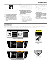
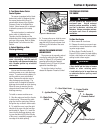
Figure 2-9: Detail – Transmission Neutral Adjustment.
P
I
X
Y
Q
M
N
O
Do not use the mower if the wheels
continue to turn after releasing the
Operator Presence Control and the
Wheel Drive Control.
Severe personal injury or property
damage could result if this instruction
is not followed.
WARNING
Unit is shipped without oil in engine
crankcase. Do not start engine until oil
has been added. Severe engine dam-
age will result if this instruction is not
followed.
CAUTION