


23
6
Maintaining
Your Lawn
Tractor
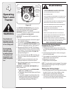
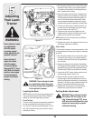
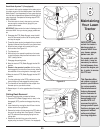
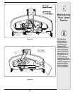
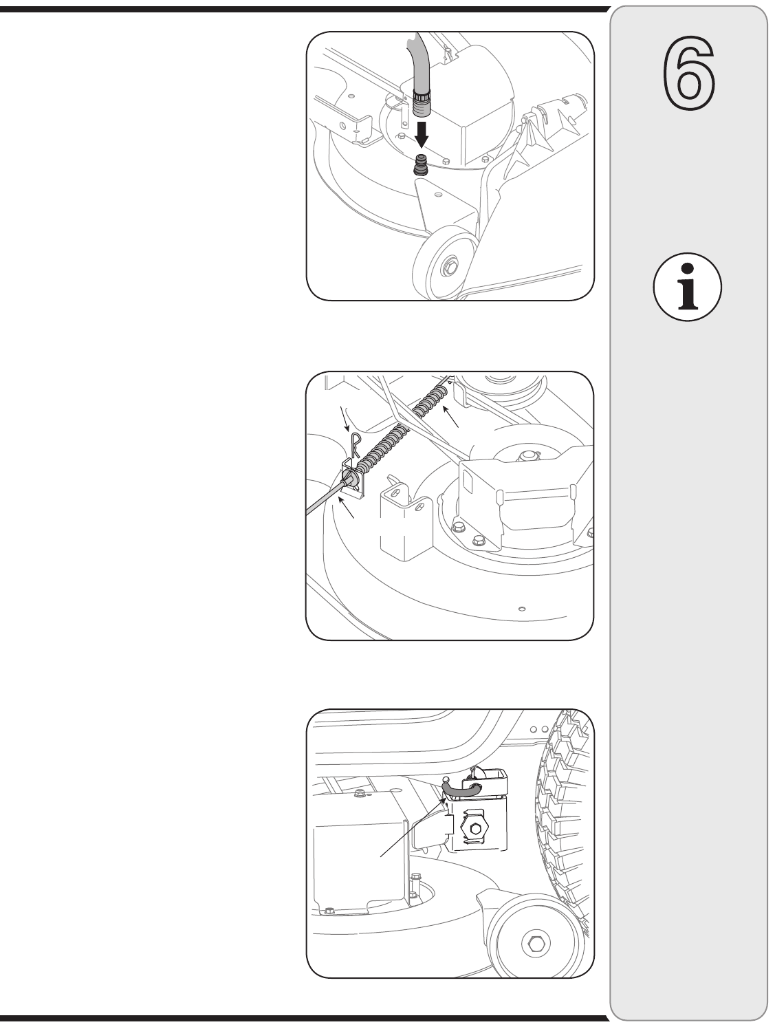
Figure 6-2
IMPORTANT: Make
certain the tractor’s
discharge chute is
directed AWAY from
your house, garage,
parked cars, etc.
Deck Wash System™ (If equipped)
Your tractor’s deck may be equipped with a water port on
its surface as part of its deck wash system. Use the Deck
Wash System™ (sold separately) to rinse grass clippings
from the deck’s underside and prevent the buildup of cor-
rosive chemicals. Complete the following steps AFTER
EACH MOWING:
1. Drive the tractor to a level, clear spot on your lawn,
near enough to a water sillcock (spigot) for your
garden hose to reach.
IMPORTANT: Make certain the tractor’s discharge chute
is directed AWAY from your house, garage, parked cars,
etc.
2. Disengage the PTO (Blade Engage), move the shift
lever into the neutral position, set the parking brake,
and stop the engine.
3. Thread the hose coupler (packaged with your tractor’s
Operator’s Manual) onto the end of your garden hose.
4. Attach the hose coupler to the water port on your
decks surface. See Figure 6-2.
5. Turn the water on.
6. While sitting in the operator’s position on the tractor,
re-start the engine and place the throttle lever in the
FAST (rabbit) position.
7. Disengage the parking brake.
8. Move the tractor’s PTO (Blade Engage) into the ON
position.
9. Remain in the operator’s position with the cutting
deck engaged for a minimum of two minutes, allowing
the underside of the cutting deck to thoroughly rinse.
10. Move the tractor’s PTO (Blade Engage) into the OFF
position.
11. Turn the ignition key to the STOP position to turn the
tractor’s engine off and engage the parking brake.
12. Turn the water off and detach the hose coupler from
the water port on your decks surface.
13. Repeat steps 4-11 on the opposite side of the cutting
deck.
Cutting Deck Removal
To remove the cutting deck, proceed as follows:
1. Place the PTO (Blade Engage) knob (or lever) in the
disengaged (OFF) position and engage the parking
brake.
2. Lower the deck by moving the deck lift lever into the
bottom notch on the right fender.
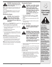
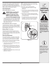
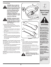
3. Remove the hairpin clip that secures the PTO cable to
the rear of the cutting deck. See Figure 6-3. Remove
the PTO cable and accompanying spring from the
cutting deck.
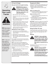
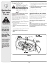
4. Remove the deck belt from around the tractor’s
engine pulley (or electric PTO clutch, if so equipped).
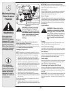
Support Pin
Figure 6-4
On models with a 46-
inch deck, it may be
necessary to remove
the belt keepers from
around the engine pul-
ley, in order to remove
the PTO belt.
PTO Cable
Hairpin Clip
Spring
Figure 6-3
This Operators Man-
ual covers a range of
product specifications
for various models.
Characteristics and
features discussed
and/or illustrated in
this manual may not
be applicable to all
models. MTD LLC
reserves the right to
change product speci-
fications, designs, and
equipment without
notice and without
incurring obligation.