


Assembly Section 3-3
ASSEMBLY
WHIRLWIND 08/01
© 2004 Alamo Group Inc.
ASSEMBLY
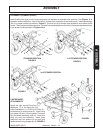
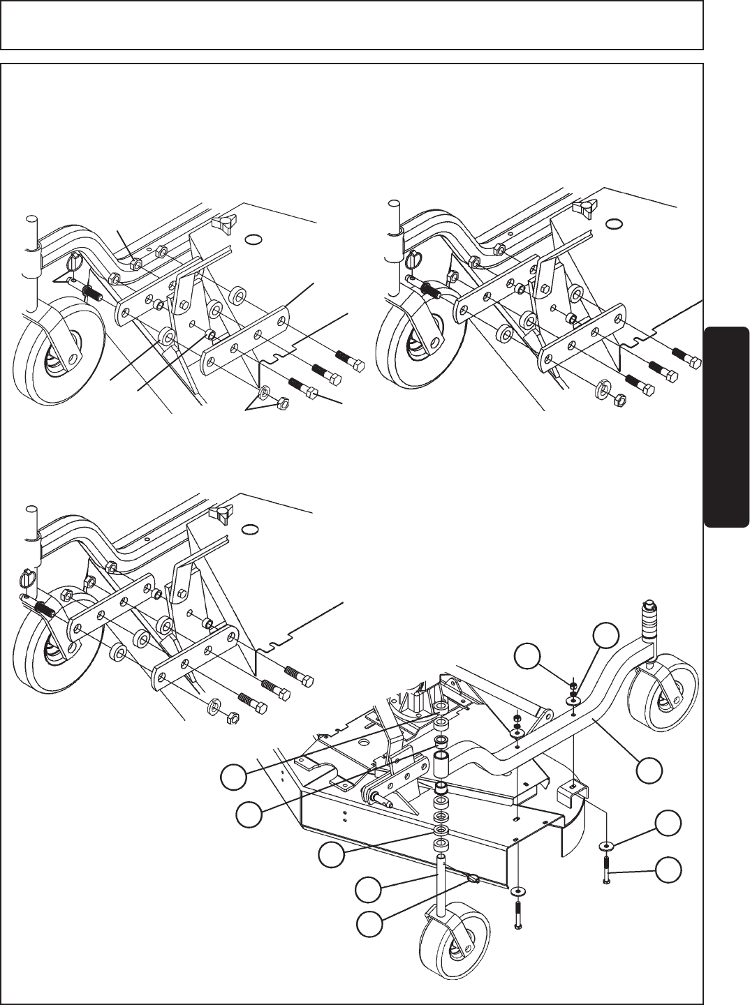
A-FRAME ATTACHMENT (cont'd.)
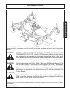
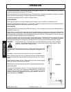
Install floating hitch pins to main frame using either the standard or extended hitch postions. See Figures 2 - 4
below for correct installation. Install hitch flats (1) to deck hitch using bolts (4) and locknuts (5), inserting bushings
(2 & 3) in proper locations as shown in Figure 2. The hitch pin (6) is always to be located on end nearest to the
tractor. There are two extended positions. To install in extended position move flats (1) forward and place bushings
in the proper locations shown in Figures 3 & 4.
STANDARD POSITION
1
ST
EXTENDED POSITION
FIGURE 3
FIGURE 4
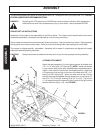
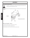
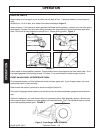
CASTER WHEEL
ATTACHMENTS
Attach the right and left Axle Arm
Weldment (1) to the deck with 3/8"
bolts (2) flatwasher (1-1/2" OD x 3/16" thick) (3),
lockwashers (4), and locknuts (5). Install a one
inch spacer (6) and a 1/2 inch spacer (7) on each
fork and wheel assembly shaft (8). Insert fork
shaft into axle arm weldment. Install three
additional one inch spacers (6) on each axle
shaft and retain using snapper pin (9). FIGURE 4.
4
3
8
5
1
8
FIGURE 2
2
ND
EXTENDED POSITION
FIGURE 4
2
1
4
5
6
7
9
2
3
8
2