


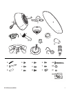

9
ETL-ES-Panorama-WH08
12
14
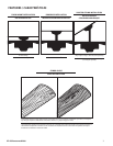
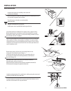
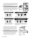
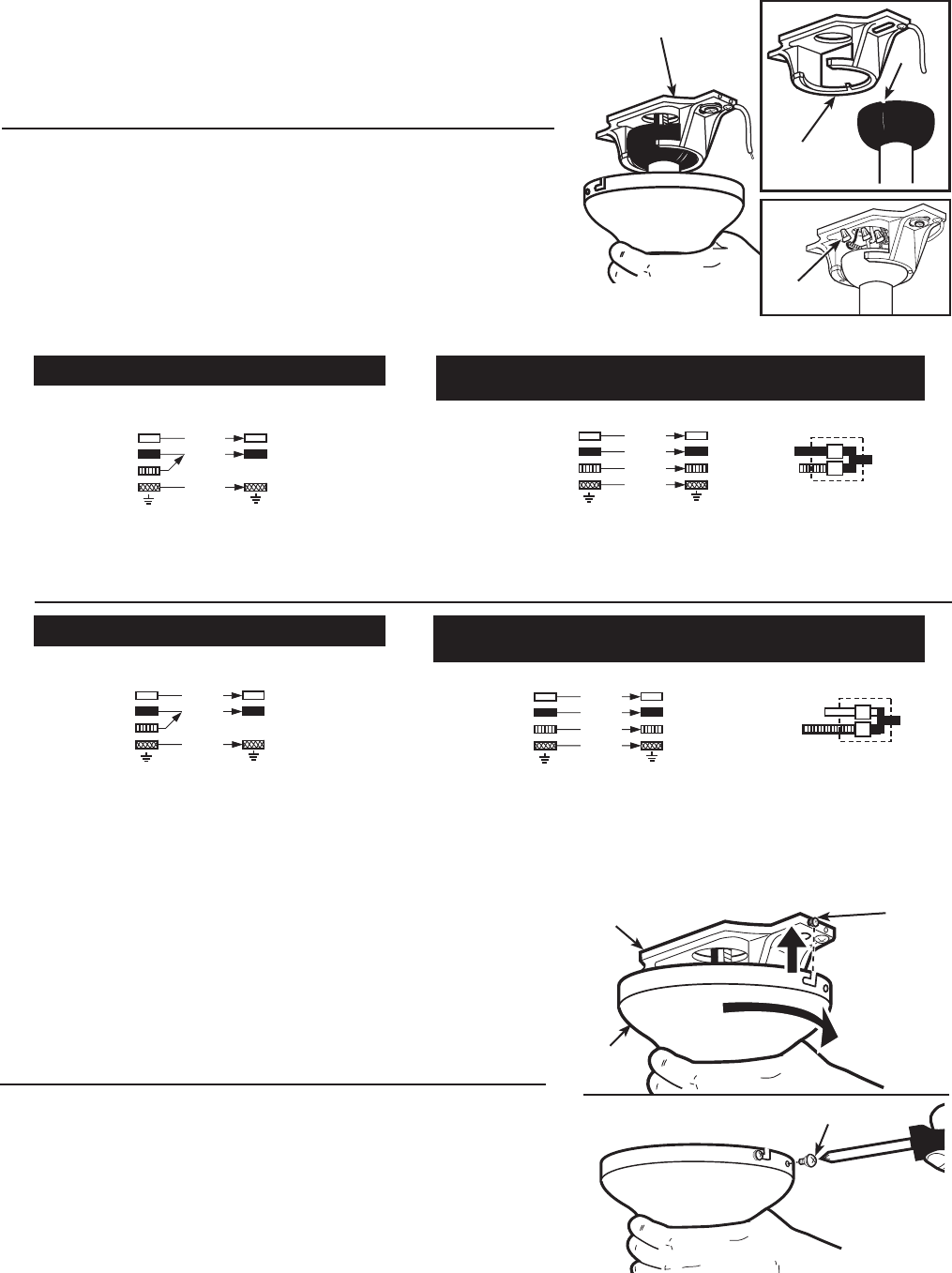
Carefully lift fan assembly onto mounting bracket (E). Rotate fan until notch
on downrod ball (F) engages the ridge on the mounting bracket (E). This will
allow for hands free wiring. With bracket holding fan assembly, make electrical
connections using the following step for wiring instructions. Make sure that
all exposed wiring is secured inside wire nuts (Z).
Levante con cuidado el conjunto del ventilador hasta el soporte de montaje (E).
Gire el ventilador hasta que la muesca de la bola de la varilla vertical (F) calce
sobre la saliente del soporte de montaje (E). De este modo, tendrá las dos manos
libres para hacer el cableado. Con la pieza de montaje sujetando el conjunto del
ventilador, haga las conexiones eléctricas de acuerdo a las siguientes instrucciones
de cableado. Asegúrese de que todos los cables expuestos estén asegurados
dentro de los conectores tipo tuerca para cables (Z).
E
E
F
Z
13
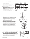
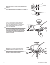
White (common)
Black (hot)
Blue* (hot)
Main (ground)
White (common)
Fan Switch (hot)
Light Switch (hot)
Green (ground)
From Fan: From House:
(connect)
(connect)
(connect)
(connect)
*Attach blue wire only if attaching light kit with fan.
Wall Control
Follow diagram above to make wiring connections for wall control
operation. NOTE: A professional electrician is recommended for this
type of installation.
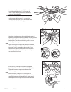
White (common)
Black (hot)
Blue* (hot)
Main (ground)
White (common)
Black (hot)
Green (ground)
From Fan: From House:
(connect)
(connect)
(connect)
*Attach blue wire only if attaching light kit with fan.
Follow diagram above to make wiring
connections for fan pull chain control.
PULL CHAIN WIRING OPTION
WALL CONTROL WIRING OPTION
(wall control switch not included)
Blanco (común)
Negro (vivo)
Azul* (vivo)
Principal (tierra)
Blanco (común)
Interruptor del ventilador (vivo)
Interruptor de la luz (vivo)
Verde (de tierra)
Del Ventilador: De La Casa:
(conectar)
(conectar)
(conectar)
(conectar)
*Conecte el cable azul sólo si conecta un juego de luces al ventilador.
Control de pared
Siga las instrucciones del diagrama anterior para hacer las conexiones
de cableado para el ventilador con control de pared. NOTA: Se
recomienda que use los servicios de un electricista profesional para
este tipo de instalación.
Blanco (común)
Negro (vivo)
Azul* (vivo)
Principal (tierra)
Blanco (común)
Negro (vivo)
Verde (de tierra)
Del Ventilador: De La Casa:
(conectar)
(conectar)
(conectar)
*Conecte el cable azul sólo si conecta un juego de luces al ventilador.
Siga las instrucciones del diagrama anterior
para hacer las conexiones de cableado para el
ventilador controlado con cadenilla de tiro.
OPCIÓN DE CABLEADO PARA CADENILLA DE TIRO
OPCIÓN DE CABLEADO PARA CONTROL DE PARED
(no está incluido el interruptor de pared)
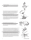
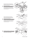
The canopy (H) has two mating slots and two mating holes. Position both
slots on canopy directly under and in line with two screws (U) in the
mounting bracket (E). Lift the canopy, allowing the two screws to slide into
the mating slots. Rotate the canopy until both screws from the mounting
bracket drop into the slot recesses. Tighten screws securely. Install two
screws (U) into the mating holes of the canopy and tighten to secure the
canopy to the mounting bracket.
El dosel (H) tiene dos ranuras coincidentes y dos orificios coincidentes. Coloque
ambas ranuras del dosel directamente abajo y en línea con los dos tornillos (U)
del soporte de montaje (E). Eleve el dosel, permitiendo que los dos tornillos se
deslicen dentro de las ranuras. Gire el dosel hasta que ambos tornillos del
soporte de montaje caigandentro de las ranuras. Apriete los tornillos
asegurándolos. Instale los dos tornillos (U) en los orificios coincidentes del
dosel y ajústelos para asegurar el dosel al soporte de montaje.
U
E
H
U