


4
MOUNTING AND WIRING INSTRUCTIONS
FIXTURE ASSEMBLY INSTRUCTIONS
NOTE: Underwriters Laboratories (UL) does not require all fixtures to have ground wires. These
fixtures meet all UL specifications
.
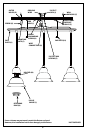
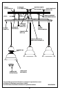
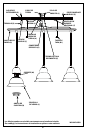
1. Beginning at sides and working at an angle, peel protective coating (if applicable) from face
plate (A) (see fig. 1).
2. Position flat side of mounting plate (C) against wall at mounting location and mark outer
holes (O) with a pencil.
NOTE: Mounting plate (C) must be level for fixture to hang straight.
3. Drill a 1/8 inch hole at each pencil mark then insert wall anchors (E) by gently tapping with a hammer.
NOTE: For added support, wall anchors and screws may also be mounted in additional support holes (F).
4. Thread outlet box wires through center opening in mounting plate (C).
5. Position mounting plate (C) with outer holes (O) over wall anchors (E) and secure with
screws (K) or secure mounting plate (C) to outlet box (J) with outlet box screws (not included).
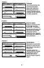
6. Identify color coding of fixture wires (see fig. 2).
7. To connect wires, take black fixture wire (group A from fig. 2) and place evenly against
black outlet box wire. Do not twist wires.
8. Fit wire connector (G from fig. 1) over wires and twist until there is a firm connection. If
wire connector (G) easily comes off, reattach and check again for a firm connection.
9. Repeat steps 7 and 8 with the white (group B from fig. 2) fixture wires and outlet box wires.
10. Partially thread green grounding screw (H) into side hole (I) on mounting plate (C) (see fig.1.)
11. Wrap ground wire from fixture around green grounding screw (H), leaving enough excess
wire to then connect ground wire and outlet box wire with wire connector (if applicable).
12. Tuck wires inside outlet box (J).
Warning: This fixture is for indoor use only.
1. Replace face plate (A) over mounting plate (C) and secure with retaining screws (B) or cap nuts (B1).
2. Place glass shade(s) (L) into holder(s) (M) and secure with retaining ring(s) (N) or thumb screws (N1).
(if applicable)
3. Install lamp(s). Do not exceed recommended wattage.
4. Turn power back on at circuit box.