


4
CAUTION: For fixtures labeled for outdoor and wet location use, provide a water-tight seal
between the fixture and the mounting surface by using silicone or similar caulking.
NOTE: Underwriters Laboratories (UL) does not require all fixtures to have ground wires. These
fixtures meet all UL specifications.
1. Turn off power at circuit box to avoid possible electric shock.
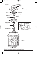
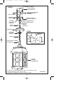
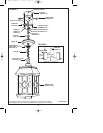
2. Secure mounting bar (A) to outlet box (B) with outlet box screws (C) (not included) (see fig. 1).
3. Install glass panels (Q) into fixture cage (G) by inserting glass panels (Q) into the fixture
cage (G) from the bottom and secure in place with clips (R) (see inset).
4. Thread hex nut (D) onto mounting nipple (E) approximately 1/4 inch and insert lock washer
(F), then thread mounting nipple (E) onto mounting bar (A) and secure with hex nut (D).
5. Open one link on bottom end of chain (J). Attach to fixture loop (I). Securely close link on
chain (J).
6. Thread screw collar ring (K) onto screw collar (L), then place canopy (M) over top of screw
collar (L).
7. Lace wires up through every other link on chain (J) then up through screw collar (L), canopy
(M) and mounting nipple (E).
8. Open one link on top end of chain (J). Attach to loop on screw collar (L). Securely close link
on chain (J).
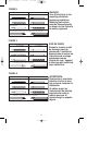
9. Identify color coding of fixture wires (see fig. 2).
10. To connect wires, take black fixture wire (group A from fig. 2) and place evenly against
black outlet box wire. Do not twist wires.
11. Fit wire connector (N from fig. 1) over wires and twist until there is a firm connection. If
wire connector (N) easily comes off, reattach and check again for a firm connection.
12. Repeat steps 10 and 11with the white (group B from fig. 2) fixture wires and outlet box wires.
13. Partially thread green grounding screw (O) into side hole (P) on mounting bar (A) (see fig. 1).
14. Wrap ground wire from fixture around green grounding screw (O) leaving enough excess
wire to then connect ground wire and outlet box wire with wire connector (N), if applicable.
15. Tighten green grounding screw (O). Do not over tighten.
16. Remove screw collar ring (K) from screw collar (L) and secure screw collar (L) to mounting
nipple (E).
17. Tuck wires inside outlet box (B).
18. Raise canopy (M) to ceiling and secure screw collar ring (K) to screw collar (L).
MOUNTING AND WIRING INSTRUCTIONS
FIXTURE ASSEMBLY INSTRUCTIONS
1. Install lamps. Do not exceed recommended wattage.
2. Turn power back on at circuit box.
12 pg_W-164_EFS 1/12/05 5:33 PM Page 4