


4
NOTE: Underwriters Laboratories (UL) does not require all fixtures to have ground wires. These
fixtures meet all UL specifications.
1. Turn off power at circuit box to avoid possible electric shock.
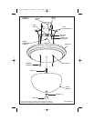
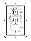
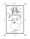
2. Thread mounting screws (A) into mounting bar (B) (see fig. 1) approximately
1
/4 inch.
3. Secure mounting bar (B) to outlet box (C) with outlet box screws (D) (not included).
4. To connect wires, take black fixture wire (group A from fig. 2 on page 11) and place evenly
against black outlet box wire. Do not twist wires.
5. Fit wire connector (E from fig. 1) over wires and twist until there is a firm connection.
If wire connector (E) easily comes off, reattach wire connector (E) and check again for a
firm connection (see figure 1).
6. Repeat steps 4 and 5 with the white (group B from fig. 2) fixture wire and outlet box wires.
7. Partially thread green grounding screw (F) into side hole (G) on mounting bar (B) (see fig. 1).
8. Wrap ground wire from fixture around green grounding screw (F), leaving enough excess
wire to then connect ground wire and outlet box wire with wire connector (E) (if applicable).
9. Tighten green grounding screw (F). Do not over tighten.
10. Tuckwires inside outlet box (C).
MOUNTING AND WIRING INSTRUCTIONS
FIXTURE ASSEMBLY INSTRUCTIONS
Warning: This fixture is for indoor use only.
1. Raise canopy (H) to ceiling allowing mounting screws (A) to protrude through key
slots (I) in canopy (H) (see fig. 1).
2. Rotate canopy (H) clockwise until mounting screws (A) lock into narrow portion of key slots (I).
3. Install lamp(s). Do not exceed recommended wattage.
4. Raise glass shade (J) to canopy (H) allowing nipple (K) to protrude through opening.
5. Carefully support glass shade (J) while securing washer (L) and finial (M) to nipple (K).
6. Turn power back on at circuit box.
12 pg_W-145_EFS 10/19/04 11:16 AM Page 4