


4
CAUTION: For fixtures labeled for outdoor and wet location use, provide a water-tight seal
between the fixture and the mounting surface by using silicone or similar caulking.
NOTE: Underwriters Laboratories (UL) does not require all fixtures to have ground wires. These
fixtures meet all UL specifications.
1. Turn off power at circuit box to avoid possible electric shock.
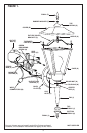
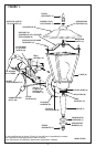
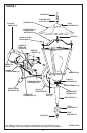
2. Remove cap nuts (A) from back plate (B) and remove universal mounting plate or cross
bar (C), leaving mounting screws (D) in place (see fig. 1).
3. Secure universal mounting plate or cross bar (C) to outlet box (E) (vertically or
horizontally, see fig. 1) with outlet box screws (F) (not included).
4. Screw center pipe (G) into bottom of cage (H).
5. Slide coupling (W) if applicable, tail (I), top break (J), and bottom break (K) over center
pipe (G) and secure with finial (L).
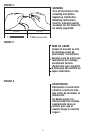
6. Identify color coding of fixture wires (see fig. 2 on page 11).
7. To connect wires, take black fixture wire (group A from fig. 2) and place evenly against
black outlet box wire. Do not twist wires.
8. Fit wire connector (M from fig. 1) over wires and twist until there is a firm connection.
If wire connector (M) easily comes off, reattach and check again for a firm connection.
9. Repeat steps 7 and 8 with the white (group B from fig. 2) fixture and outlet box wires.
10. Partially thread green grounding screw (N) into side hole (O) on universal mounting
plate or cross bar (C) (see fig.1).
11. Wrap ground wire from fixture and ground wire (metal or green wire) from outlet box
(E) around green grounding screw (N) on universal mounting plate or cross bar (C).
12. Tighten green grounding screw (N). Do not over tighten.
13. Tuck wires inside outlet box (E) (see fig. 1).
MOUNTING AND WIRING INSTRUCTIONS
FIXTURE ASSEMBLY INSTRUCTIONS
1. Place back plate (B) over mounting screws (D) and secure with cap nuts (A).
2. Install lamp(s). Do not exceed recommended wattage.
3. Remove finial (P), rubber washer (T) and top break (Q) from cover (R) then separate
fixture cover bracket (S) from cover (R).
4. Remove threaded cap nuts (V) from top of cage (H) (do not remove remaining 2
cap nuts).
5. Mount fixture cover bracket (S) over holes as shown in figure 1 and secure with
threaded cap nuts (V).
6.
Place cover (R) over nipple (U) and secure with top break (Q) and finial (P).
7. Turn power back on at circuit box.