


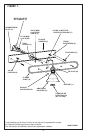

4
NOTE: Underwriters Laboratories (UL) does not require all fixtures to have ground wires. These
fixtures meet all UL specifications.
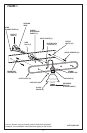
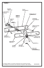
1. Turn off power at circuit box to avoid possible electric shock.
2. Beginning at sides and working at an angle, peel protective coating (if applicable) from
face plate (A) (see fig. 1).
3. Remove cap nuts (B) from face plate (A) and remove back plate (C), leaving mounting
screws (D) in place.
4. Secure back plate (C) to outlet box (E) using outlet box screws (F) (not included).
NOTE: For maximum support, use wood screws (O) in outer holes (G) (or toggle bolts if outer
holes (G) meet sheetrock).
5. To connect wires, take black fixture wire (group A from fig. 2 on page 11) and place evenly
against black outlet box wire. Do not twist wires.
6. Fit wire connector (H from fig. 1) overwires and twist until there is a firm connection.
If wire connector (H) easily comes off, reattach and check again for a firm connection
(see figure 1).
7. Repeat steps 5 and 6 with the white (group B from fig. 2) fixture and outlet box wires.
8. Partially thread green grounding screw (I) into side hole (J) on back plate (C) (see fig.1).
9. Wrap ground wire from fixture and ground wire (metal or green wire) from outlet box
(E) around green grounding screw (I) on back plate (C).
10. Tuckwires inside outlet box (E).
MOUNTING AND WIRING INSTRUCTIONS
FIXTURE ASSEMBLY INSTRUCTIONS
1. Place face plate (A) over back plate (C) and secure with cap nuts (B).
2. Secure glass shade(s) (K) into holder(s) (L) with thumb screws (M) or retaining ring(s)
(N), whichever is applicable.
3. Install lamp(s). Do not exceed recommended wattage.
4. Turn power back on at circuit box.