


4
CAUTION: For fixtures labeled for outdoor and wet location use, provide a water-tight seal
between the fixture and the mounting surface by using silicone or similar caulking.
NOTE: Underwriters Laboratories (UL) does not require all fixtures to have ground wires. These
fixtures meet all UL specifications.
1. Turn off power at circuit box to avoid possible electric shock.
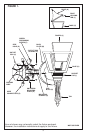
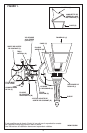
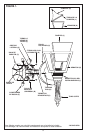
2. Thread mounting screws (A) into the universal mounting plate (B) (see figure 1).
3.
Secure universal mounting plate (B) to outlet box (C) with outlet box screws (D) (not included)
.
NOTE: Mounting screws must be level for fixture to hang straight.
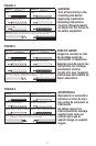
4. Identify color coding of fixture wires (see figure 2 on page 11).
5. To connect wires, take black fixture wire (group A from figure 2) and place evenly against
black outlet box wire. Do not twist wires.
6. Fit wire connector (E from figure 1) overwires and twist until there is a firm connection. If
wire connector (E) easily comes off, reattach wire connector (E) and check again for a firm
connection (see figure 1).
7
. Repeat steps 5 and 6 with the white (group B from figure 2) fixture wire and outlet box wires.
8. Partially thread green grounding screw (F) into side hole (G) on universal mounting
plate (B) (see figure 1).
9. Wrap ground wire from fixture and ground wire (metal or green wire) from outlet box (C)
around green grounding screw (F) on universal mounting plate (B).
10. Tighten green grounding screw (F). Do not over tighten.
MOUNTING AND WIRING INSTRUCTIONS
FIXTURE ASSEMBLY INSTRUCTIONS
1. Assemble cage (H) by lining up tabs on socket cup (I) with slots in bottom of cage (H)
(if applicable) (see figure 1).
2. Twist clockwise to lock in place.
3. Install panels (J) (textured side in) into cage (H).
4. Attach roof (K) by snapping pins into corresponding holes in roof.
5. Install lamp(s). Do not exceed recommended wattage.
6. Secure roof (K) by bending roof locking tab (L) inward approximately
1
/4” and snapping
into place.
7. Tuckwires inside outlet box (C).
8. Place back plate (M) over mounting screws (A).
9. Secure into place with cap nuts (N).
10.Turn power back on at circuit box.