


4
CAUTION: For fixtures labeled for outdoor and wet location use, provide a water-tight seal
between the fixture and the mounting surface by using silicone or similar caulking.
NOTE: Underwriters Laboratories (UL) does not require all fixtures to have ground wires. These
fixtures meet all UL specifications.
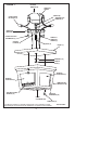
1. Turn off power at circuit box to avoid possible electric shock.
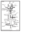
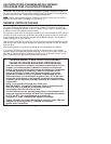
2. Thread nipple (A) into center hole on mounting bar (B) approximately
3/4 inch (see fig. 1).
3. Secure lockwasher (C) and nut (D) to nipple (A) on back side of mounting bar (B).
4. Secure mounting bar (B) to outlet box (E) with outlet box screws (F) (not included).
5. Identify color coding of fixture wires (see figure 2 on page 11).
6. To connect wires, take black fixture wire (group A from fig. 2) and place evenly against
black outlet box wire. Do not twist wires.
7. Fit wire connector (G from fig. 1) over wires and twist until there is a firm connection.
If wire connector (G) easily comes off, reattach and check again for a firm connection
(see fig. 1).
8.
Repeat steps 6 and 7with the white (group B from fig. 2) fixture and outlet box wires.
9. Partially thread green grounding screw (H) into side hole (I) on mounting bar (B) (see fig. 1).
10. Wrap ground wire from fixture and ground wire (metal or green wire) from outlet box
(E) around green grounding screw (H) on mounting bar (B).
11. Tighten green grounding screw (H). Do not over tighten.
12. Tuck wires inside outlet box (E).
MOUNTING AND WIRING INSTRUCTIONS
FIXTURE ASSEMBLY INSTRUCTIONS
1. Raise canopy (J) to ceiling with nipple (A) protruding through center hole of canopy (J)
(see fig. 1).
2. Secure into place with washer (K) and cap nut (L).
3. Install lamp(s). Do not exceed recommended wattage.
4. Install square panel (M), textured sides facing outward, into bottom of fixture cage (N).
(see figure 1).
5. Center four panel brackets (O) on each edge of square panel (M) (see fig. 1).
6. Insert side panels (P), textured side facing outward, behind interior corner slots (Q) of
fixture cage (N).
NOTE: When side panels (P) are inserted into panel brackets (O), brackets will snap upward to
secure panels into place. If needed, gently push side panels (P) down until brackets snap into
place. After assembly, do not push on panels from the exterior of the fixture cage (N).
7. Raise fixture cage (N) to canopy (J), lining up holes in canopy (J) with holes in fixture
cage (N), and secure with screws (R).
8. Turn power back on at circuit box.