


4
ASSEMBLY
WARNING: If received assembled,
reviewall assembly steps to ensure yourunit
is properly assembled and all fasteners are
secure.
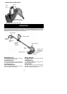
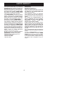
TUBE ASSEMBLY
2. A
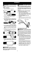
1. Remove the wire protector from the
tubes and discard.
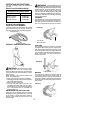
lign upper tube groove with triangle on
lower locking sleeve assembly. Push
tubes together until they snap into place.
Alignment Triangle
Upper Tube
Groove
3. Try to pull tubes back apart. If the tubes do
not come apart, they are properly snapped
into place. If the tubes come apart, repeat
step 1 and push until the tubes snap into
place.
4. Slideupperlockingsleeveassemblyover
lower locking sleeve assembly and tight-
en by turning clockwise.
5. Ensure locking sleeve assembly and
alignmentdecalsappearasillustratedbe-
low.
Alignment decals
WARNING: Failure to completely en-
closeexcess wires inuppertubeduringassem-
bly of theunitmay resultindamagetothewires
and/or the unit or serious injury to the operator
including electrocution.
WARNING: The upper and lower
tubesmust besnapped together, remain per-
manentlyassembledtogetherandthelocking
sleeve assembly must be fully tightened be-
fore and during use to avoid serious injury to
the operator and/or damage to the unit. DO
NOT attempt to disassemble unit after initial
assembly.
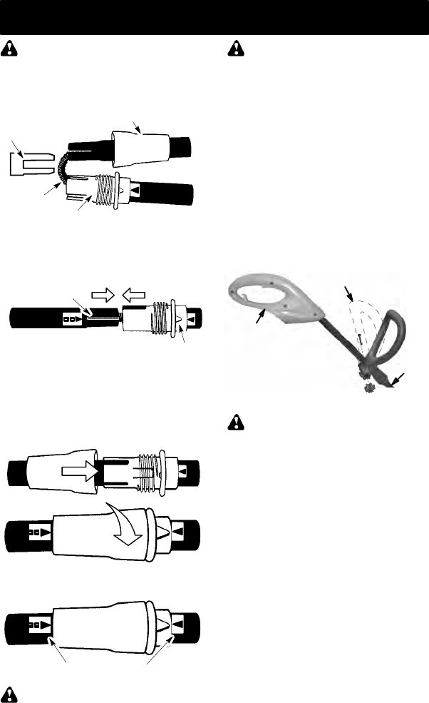
INSTALLATION OF ASSIST HANDLE
1. Place unit on a flat surface.
2. Remove knob and bolt from kit.
3. Firmly push the assist handle over the
tube. Tomake installationeasier, tilthan-
dle tow
ard trigger housing while pushing
down (see illustration).
4. Install bolt in handle. Thread knob
onto bolt.
5. Adjustthehandleupordownthetubetoa
comfortable postion; tighten knob secure-
ly.
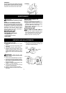
ATTACHING TH E SHIELD
WARNING: Theshieldmustbeprop-
erly installed. The shield provides partial
protection from the risk of thrown objects to
theoperatorandothers.Yourunitis equipped
with a line limiter blade, which cuts excess
line to the proper length while running. The
line limiter blade (on underside of shield) is
sharp and can cut you.
NOTE: If shield is notproperly installed,dam-
age to unit (including motor failure) will result.
1. Insert the shield onto the motor housing.
Ensure the cutting head remains free to
r
otate and the line is not caught between
the shield and the motor housing (See
following illustration).
2. Twist the shield as illustrated until the
hole in the shield aligns with the hole in
the housings.
3. Install bolt into shield and motor hous-
ing as shown. Tighten securely.
Make sure
the shield
is
assembled to the unit as shown in the
illustration below and in the KNOW
YOUR UNIT section of this manual.
Assist handle
Tube
Trigger
housing
Wire protector
Upper Locking Sleeve Assembly
Lower Locking Sleeve Assembly
Wires