5
OPERATION
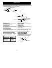
KNOW YOUR TRIMMER
READ THIS INSTRUCTION MANUAL AND SAFETY RULES BEFORE OPERATING YOUR UNIT.
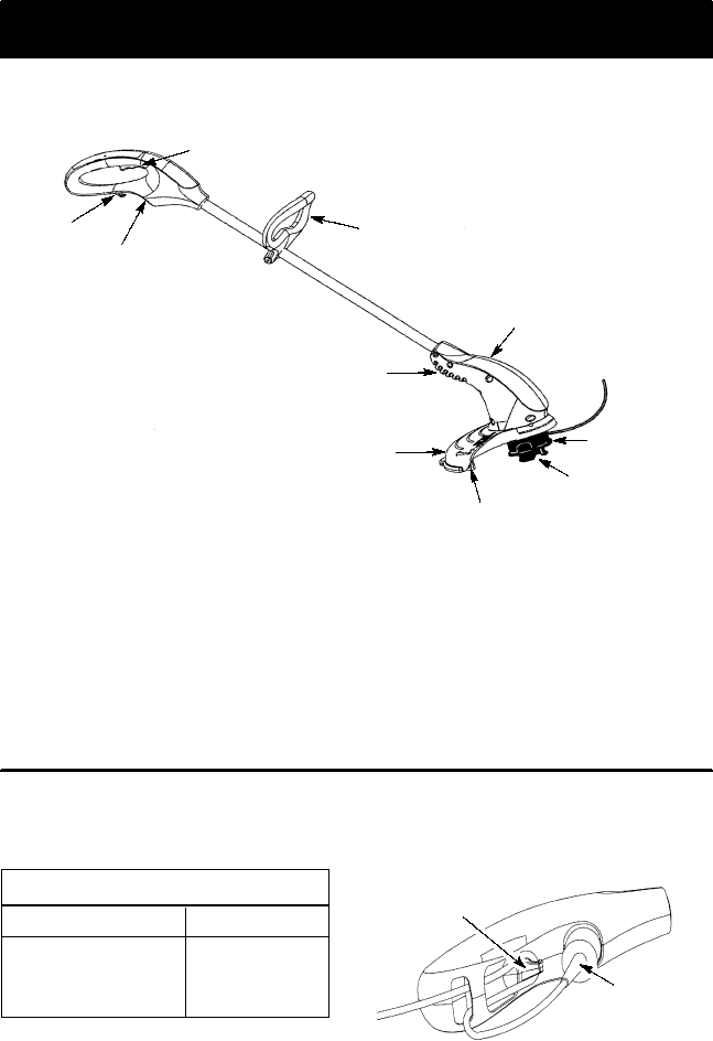
Compare the illustrations with yourunit to familiarize yourself with the locatio n of the variou s controls
and adjustments. Save this m anual for future reference.
Recessed
Plug
Trigger Switch
Cord
Retainer
Air Vents
Debris Shield
Line Limiter Blade
Motor Housing
Trimmer Head
with 0.065 in.
Trimmer Line
Assist Handle
Tap Button
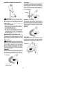
RECESSED PLUG
The RECESSED PLUG is where you attach
your extension cord to the unit.
TRIGGER SWITCH
TheTRIGGER SWITCHisused toturn onthe
unit. Squeeze the trigger switchto operate the
unit. Release to stop.
LINE LIMITER BLADE
The LINE LIMITER BLADE cuts the cutting
line to the proper cutting length.
ASSIST HANDLE
The ASSIST HANDLE is used to help hold
and guide the unit.
TRIMMER HEAD
The TRIMMER HEAD holds cutting line and
rotates during operation.
TAP BUTTON
The TAP BUTTON is used to advance the
cutting line during operation and to remove
the spool during line replacement.
OPERATING INSTRUCTIONS
Use only a voltage supply as specified on
your unit.
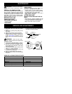
SELECT AN EXTENSION CORD
Extension Cord Gauge Chart
Length of Cord Gauge
25 Ft. (7.5 m)
50 Ft. (15 m)
100 Ft. (30 m)
18 Gauge
16 Gauge
16 Gauge
Extension cords are available for this unit.
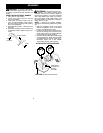
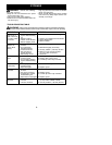
ATTACH THE EXTENSION
CORD TO YOUR TRIMMER
Loop your extension cord through the handle
and around the hook as shown. Insure the
plug and cord are firmly and fully engaged.
Cord Retainer
Extension Cord


