


5
ASSEMBLY
WARNING:
Stop the unit and
disconnect from the power source be-
fore opening the inlet cover or attempt-
ing to insert or remove the inlet restrictor ,
blower tube, or vacuum tubes. T he mo-
tor must be stopped and the impeller
blades no longer turning to avoid serious
injury from the rotating blades.
WARNING:
If received as-
sembled, ensure your unit is properly
assembled and all fasteners are secure.
S
A standard screwdriver is required for
assembly.
BLOWER ASSEMBLY
NOTE: Assem bly instructions for using
your unit a s a vacuum follow this section.
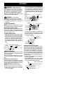
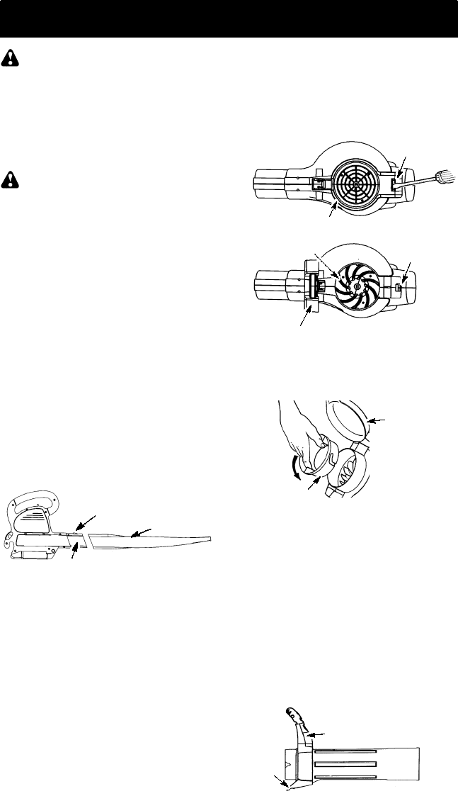
Attaching the blower tube
If you have already assembled your unit
for use as a vacuum, refer to the section
HOW TO CONVERT UNIT FROM VACUUM
USE TO BLOWER USE.
To attach blower tube:
S
Align the grooves on the blower tube
with the grooves on the blower outlet.
S
Push the blower tube onto the blower
outlet until it snaps into place (tube is
secured by red tube release button).
S
To remove the blower tube, press the
tube release button while pulling on
tube.
Blower Tube
Blower outlet
Tube Release Button
VACUUM ASSEMBLY
NOTE: Assembly instructions for using
your unitas ablower areexplained inthe
previous section.
If you have already assembled your unit
for use as a blower, remove the blower
tube.
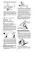
Remove the inlet restrictor
An inlet restrictor is used when using your
unit as a blower . This restrictor is not used
during vacuum use and must be r emoved
during assembly for v acuum use.
NOTE: Be sure to keep the inlet re-
strictor for using your unit as a blower.
S
Ensure unit is stopped and extension
cord is unplugged.
S
Open the inlet cover by inserting the
tip of a screwdriver into the latch area
on the blower unit. Gently tilt handle of
screwdriver toward the front of the unit
to release the latch while pulling upon
the vacuum inlet cover with your other
hand.
Vacuum Inlet Cover (closed)
Latch Area
Bottom view
of unit
Vacuum Inlet Cover (opened)
Latch Area
Impeller
S
T urn the i nlet restrictor counterclock-
wise and remove it from the unit. Donot
close the inlet door. You will next attach
the vacuum tubes.
Inlet
Restrictor
Vacuum
Inlet Cover
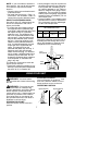
Attaching the vacuum tubes
There are 2 vacuum tubes, an upper
tube and a lower tube. The upper tube
has a vacuum assist handle attached to
oneend andis cutstraight on both ends.
The upper tube attaches to the blower
unit. The lower tube has an angled end
that you point toward the ground during
vacuumuse. Thelower tubeattaches to
the upper tube.
S
Ensure unit is stopped and extension
cord is unplugged.
S
While holding inlet cover open, place
the hooks of the vacuum assist handle
on the retaining posts of the unit.
Upper Vacuum T ube
Vacuum Assist Handle
Hook