


10
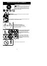
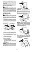
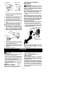
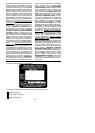
Hub
Line in Notch
Line in Notch
Line exit holes
5. W ind the line evenly and tightly onto the
spool. Wind in the direction of thearrows
found on the spool.
6. P ushthelines into thenotches, leaving 3
to 5 inches (7 -- 12 cm) unwound.
7. I nsert the lines into the the exit holes in
the hub as shown in the illustration.
8. A lign thenotches with the line exit holes.
9. P ush spool into hub until it snaps into
place.
10. Pullthelinesextendingoutsideofthehub
to release t he lines from the notches.
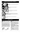
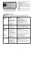
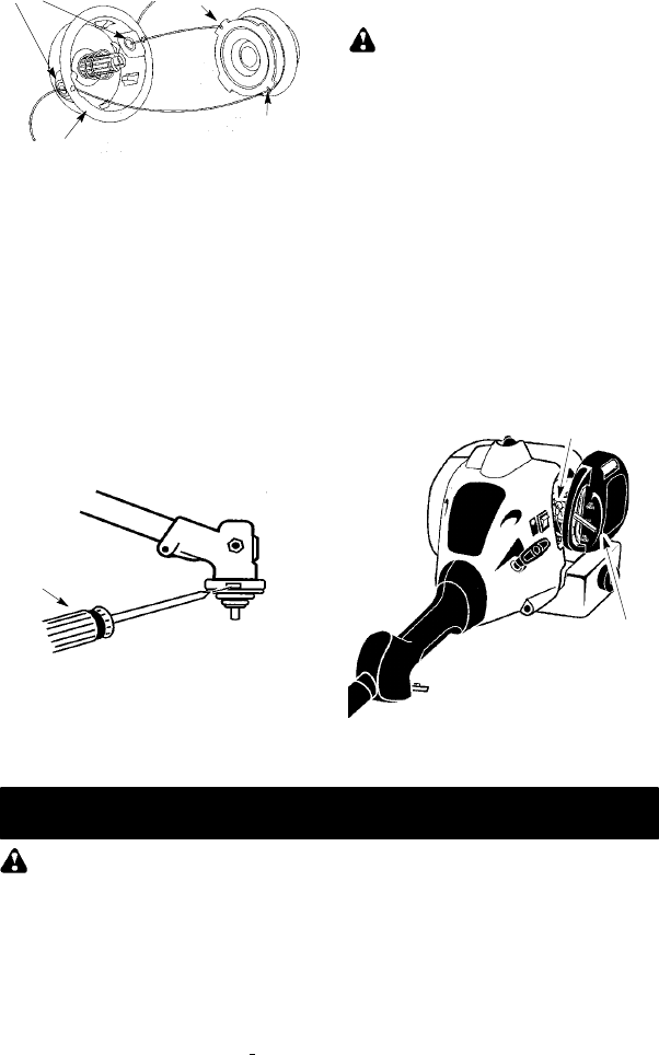
REPLACING THE CUTTING HEAD
1. Alignholeinthe dustcup withthehole inthe
side ofthe gearboxby rotatingthe dustcup.
2. Insert a small screwdriver into aligned
holes. This will keep the shaft from turning
while removing andinstalling trimmer head.
Screwdriver
3. While holding the screwdriver in position,
remove trimmer head by turning clockwise
(looking from bottom o f unit).
4. Thread replacement trimmer head onto the
shaft by turning counterclockwise. Tighten
until secure.
5. Remove the screwdriver.
CARBURETOR IDLE SPEED
ADJUSTMENT
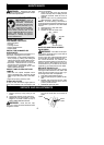
WARNING: Keep others away when
making idlespeedadjustments. The trimmer
head will be spinning during this procedure.
Wearyour protectiveequipmentand observe
all safety precautions.
The carburetor has been carefully set at the
factory .Adjustments maybenecessary ifyou
notice any of the following conditions:
S Engine will not idl e when the throttle i s re-
leased.
Make adjustments with the unit supported so
the cutting attachment is off the ground and
will not make contact with any object. Hold
theunitby handwhilerunningandmakingad-
justments. Keep all parts of your body away
from the cutting attachment an d muf fler.
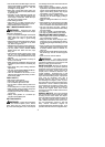
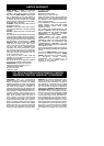
To adjust idle speed:
Allowengine toidle.Adjustspeeduntilengine
runs without stalling (idle speed too slow).
S Turn idle speed screw clockwise to in-
creaseenginespeedifenginestalls ordies.
S Turn idle speedscrew counterclockwise to
decrease engine speed.
Air Filter Cover
Idle Speed Screw
Ifyourequirefurtherassistanceorareunsure
about performing this procedure, contact an
authorized service dealer or call
1--800--554--6723.
STORAGE
WARNING: Perform t he following
steps after each use:
S Allow engine to cool, and secure the unit
before storing or transporting.
S Store unit and fuel in a well ventilated area
where fuel vapors cannot reach sparks or
open flames from water heaters, electric
motors or switches, f urnaces, etc.
S Store unit with all guards in place. Position
unit so that any sharp object cannot acci-
dentally cause injury.
S Store unit and fuel well out of the
reach o f
children.
SEASONAL STORAGE
Prepareunit forstorage atend ofseason or if
it will not be used for 30 days or more.
If your unit is to be stored for aperiod of time:
S Clean the entire unit before lengthy storage.
S Store in a clean dry area.
S Lightly oil external metal surfaces.
FUEL SYSTEM
Under FUELING ENGINE i n t he OPERA-
TIONsectionofthis manual,seemessagela-
beled IMPORTANT regarding the use of ga-
sohol in your engine.
Fuel stabilizer is an acceptable alternative in
minimizing theformation offuel gumdeposits
during storage. Add stabilizer to the gasoline
in the fuel tank or fuel storage container. Fol-
low the m ix instructions found on stabilizer
container.Run engineat least5 minutesafter
adding stabilizer.