


5
ASSEMBLY
WARNING: Stop the unit a nd dis-
connect from the power source befor e
opening the inletcover or at t empt i ng to in-
sert or remove the inlet restrictor , blower
tube, or vacuum tubes. The motor must
be stopped and the impel l er b l ades no
long er turning to avoid serious injur y from
the r otat i ng bl ades.
WARNING: I f recei ved a ssem bled,
ensur e your unit is pro perl y assem bled
and all f astener s ar e secure.
S A s tand ard screwdriver is required f o r as-
sembly.
BLOWER ASSEMBLY
NOTE: Assembly instruct ions for using
your uni t as a v acuum fol l ow t hi s s ecti on.
Attaching the blower tube
Ifyou have alreadyassembled your unit
for use as av acuum, referto the section
HOW TO CONVERT UNIT FROM VACUUM
USE TO BLOWER USE.
To attach blower tube:
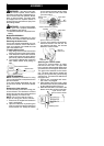
1. Align thegrooves on the blowertube
with the groovesonthe bloweroutlet.
2. Push theblowertubeontotheblower
outletu ntilitsnap s into place (tube is
secured by red tube release button).
3. To remove the bl ower tube, pr ess the
tube release button while pulling on
tube.
Blower Tube
Blower outlet
Tube Release Button
VACUUM ASSEMBLY
NOTE: Assembly instructions for using
yourunitasablowerareexplainedinthe
previous section.
If you have alr eady assem bled your unit
for use as a blower, rem ove the blow er
tube.
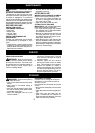
Remove the inlet restrictor
An inlet r estrictor is used when using your
unit as a blower. This restr ict or i s not used
during vacuum use and must be r emoved
during assembly f or v acuum use.
NOTE: Be sure to keep the inlet re-
strictor for using your unit as a blower.
1. Ensure unit i s stopped and extension
cord is unplugged.
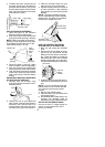
2. Open the inlet cover by inserting the
tipofa screwdriverintothe latcharea
on the blower unit. Gently tilt handle
of screwdriver toward the front of the
unit to release the latch while pulling
up on the vacuu m inlet cover with
your other hand.
Vacuum Inlet Cover (closed)
Latch Area
Bottom view
of unit
Vacuum Inlet Cover (opened)
Latch Area
Impeller
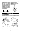
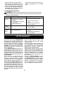
3. T urn the inlet restrictor counterclock-
wise and remove it from the unit. Do
not close the i nl et door. You will next
att ach the vacuum tubes.
Inlet
Restrictor
Vacuum
Inlet C over
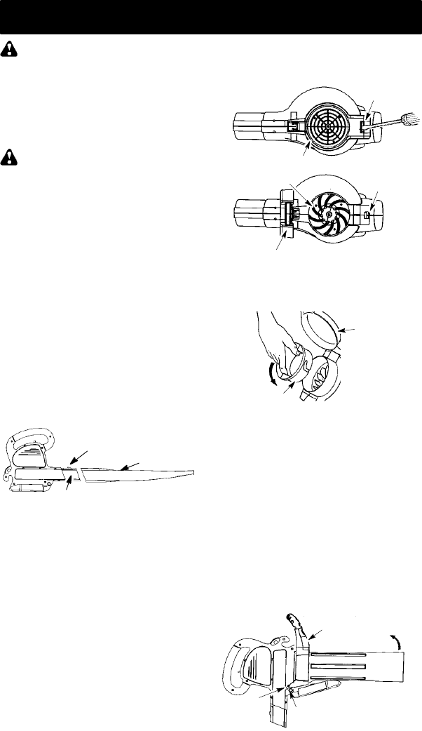
Attaching the vacuum tubes
There are 2 v acu um tubes, an upper
tube and a lower tube. The upper tube
has a vacuum assist handle attached to
oneend andiscut straightonboth ends.
The upper tube attaches to the blower
unit. The lower tube has a n angled end
that you point toward the ground during
vacuumuse. Thelowertubeattachesto
the upper tube.
1. Ensure unit is stopped and exten-
sion cord is unplugged.
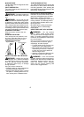
2. Whi l e holding inlet cover open, place
th ehooks of thevacuum assisthandl e
on t h e retaini ng posts of the unit.
3. Raise the tube u nti l i t is secured to the
blower uni t by the red inlet cover latch.
Retaining Post
Vacuum Assist Handle
Upper
V
acuum Tube
Hook