


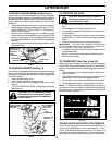

21
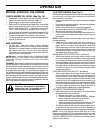
SERVICE AND ADJUSTMENTS
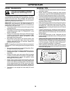
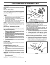
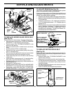
NUT "E"
"D"
"D"
MANDREL
FIG. 20
NUT "F"
FRONT LINKS
FIG. 21
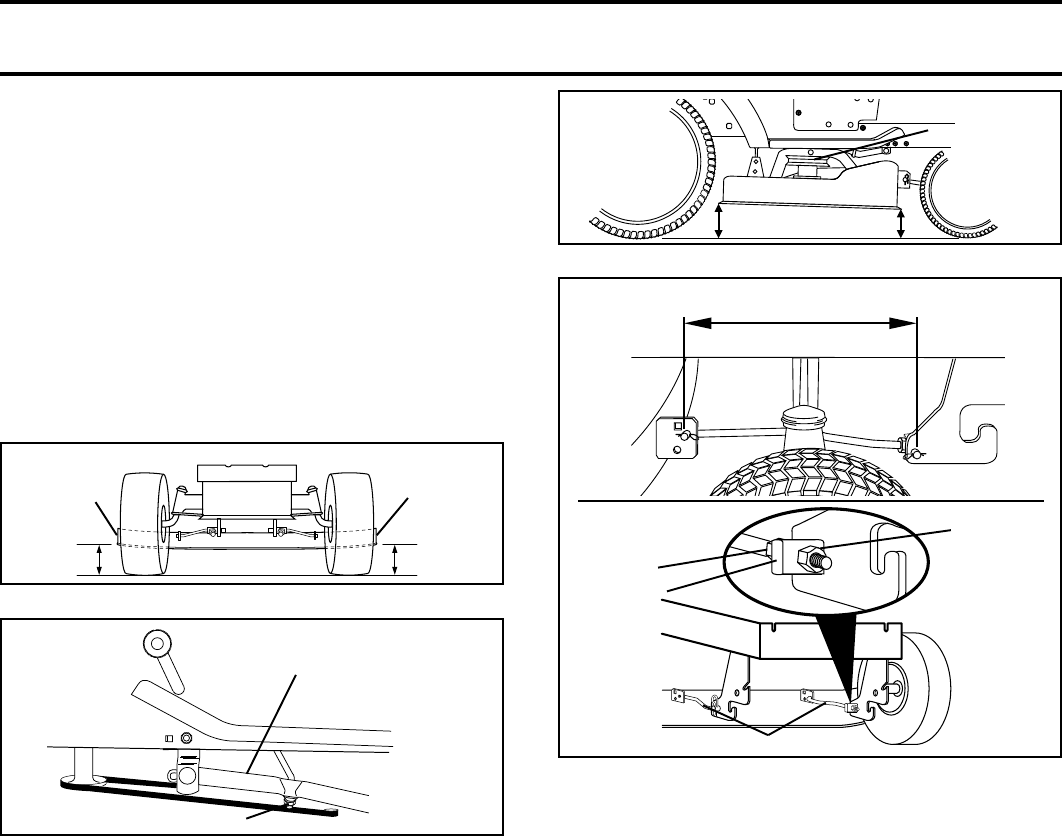
FRONT-TO-BACK ADJUSTMENT (See Figs. 20 and 21)
IMPORTANT: DECK MUST BE LEVEL SIDE-TO-SIDE. IF
THE FOLLOWING FRONT-TO-BACK ADJUSTMENT IS
NECESSARY, BE SURE TO ADJUST BOTH FRONT LINKS
EQUALLY SO MOWER WILL STAY LEVEL SIDE-TO-
SIDE.
To obtain the best cutting results, the mower housing should
be adjusted so that the front is approximately 1/8" to 1/2"
lower than the rear when the mower is in its highest position.
Check adjustment on right side of tractor. Measure distance
“D” directly in front and behind the mandrel at bottom edge
of mower housing as shown.
• Before making any necessary adjustments, check that
both front links are equal in length. Both links should be
approximately 10-3/8".
• If links are not equal in length, adjust one link to same
length as other link.
• To lower front of mower loosen nut “E” on both front links
an equal number of turns.
• When distance “D” is 1/8" to 1/2" lower at front than rear,
tighten nuts “F” against trunnion on both front links.
• To raise front of mower, loosen nut “F” from trunnion on
both front links. Tighten nut “E” on both front links an
equal number of turns.
• When distance “D” is 1/8" to 1/2" lower at front than rear,
tighten nut “F” against trunnion on both front links.
• Recheck side-to-side adjustment.
BOTH FRONT LINKS MUST BE EQUAL IN LENGTH
FIG. 18
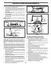
SUSPENSION ARM
LIFT LINK ADJUSTMENT NUT
FIG. 19
“A”
“A”
BOTTOM EDGE
OF MOWER
TO GROUND
BOTTOM EDGE
OF MOWER
TO GROUND
GROUND LINE
TRUNNION
SIDE-TO-SIDE ADJUSTMENT (See Figs. 18 and 19)
• Raise mower to its highest position.
• At the midpoint of both sides of mower, measure height
from bottom edge of mower to ground. Distance “A” on
both sides of mower should be the same or within 1/4"
of each other.
• If adjustment is necessary, make adjustment on one
side of mower only.
• To raise one side of mower, tighten lift link adjustment
nut on that side.
• To lower one side of mower, loosen lift link adjustment
nut on that side.
NOTE: Three full turns of adjustment nut will change mower
height about 1/8".
• Recheck measurements after adjusting.
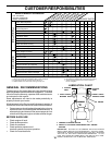
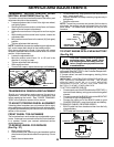
TO REPLACE MOWER DRIVE BELT
MOWER DRIVE BELT REMOVAL (See Fig. 22) -
• Park tractor on a level surface. Engage parking brake.
Disengage attachment clutch control.
• Remove screws from L.H. mandrel cover and remove
cover.
• Remove small retainer spring and lift clutch spring off
pulley bolt.
• Roll belt over the top of L.H. mandrel pulley.
• Remove belt from engine pulley.
• Remove belt from idler pulleys.
• Remove any dirt or grass clippings which may have
accumulated around mandrels and entire upper deck
surface.
• Check primary idler arm and two idlers to see that they
rotate freely.
MOWER DRIVE BELT INSTALLATION (See Fig. 22) -
• Install belt in both idlers. Make sure belt is in both belt
keepers at the idlers as shown.
• Install new belt onto engine pulley.
• Roll belt into upper groove of L.H. mandrel pulley.
• Carefully check belt routing making sure belt is in the
grooves correctly and inside belt keepers.
• Reassemble clutch spring to pulley bolt.
• Reassemble L.H. mandrel cover.