


2
Operating Instructions and Parts Manual
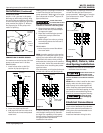
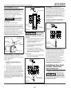
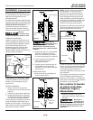
DISCHARGE PIPING
Install a 1-1/2” pipe tee in the pump
discharge to allow easy priming. Plug
the end of the tee opposite the pump
to allow the branch piping to go to the
spray nozzles (See Figure 1). Remove
the pipe plug to fill the pump with
water for priming.
CONNECTION TO WATER SOURCE
The maximum vertical suction lift from
pump to the water level is 25 feet.
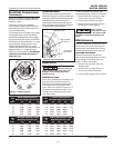
DRILLED WELL
1. Install a foot valve on the first
section of pipe (see Figure 2).
2. Lower the pipe into the well.
3. Add pipe until the foot valve is 10
feet below the lowest anticipated
water level.
Leaking joints or couplings will allow air
to leak into the pipe and cause poor
pump operation. Make sure to use pipe
joint compound or Teflon
®
tape on all
pipe connections.
Locate foot valve
no closer than 2 feet
from the bottom of the well so sand or
sediment is not drawn into the system.
4. After the proper depth is reached,
install a well seal or pitless adapter
to support the pipe.
5. Slope the horizontal pipe upward
toward the pump to eliminate
trapping air.
6. When using a foot valve, a priming
tee and plug above the well seal is
recommended.
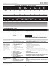
DRIVEN WELL
• Drive the point several feet below
the water table.
NOTE: A packer-type foot valve can be
installed in the well (See Figure 3). This
type of foot valve allows the well pipe
to be filled with water when priming
and makes the inlet pipe much easier to
test for leaks. Follow the manufacturer’s
instructions when installing the packer-
type foot valve.
As an alternative, an in-line check valve can
be used with a driven well (See Figure 4).
It may be necessary to supply the pump
with multiple well points to maintain
the high flow capability of this pump.
Consult with a plumbing professional
for appropriate materials and
installation instructions.
Leaking joints or couplings will allow air
to leak into the pipe and cause poor
pump operation. Make sure to use pipe
joint compound or Teflon
®
tape on all
pipe connections.
Dug Well, Cistern, Lake
And Spring Installation
• Install a foot valve on the inlet pipe
and lower into the water.
Locate foot valve no
closer than 2 feet
from the bottom of the water source so
sand or sediment is not drawn into the
system.
NOTE: When a lake is used for the water
supply, make sure the suction pipe is
deep enough to be submerged at all
times. Slope the pipe upward toward
the pump to eliminate trapping air. The
pipe must be removed during winter
months or protected against freezing.
Protect the pipe
from damage by
swimmers and boaters.
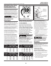
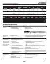
Electrical Connections
Connect the pump to a separate electrical
circuit with a dedicated circuit breaker.
Refer to the electrical specifications in
wiring chart for recommended circuit
breaker and wire size.
Install and maintain wiring for this
To Pump
Well Seal
Well
Casing
Foot Valve
Figure 2
Drive Point
Figure 3
To Pump
Packer Type
Foot Valve
To Pump
Inline Check Valve
Drive Point
Figure 4
Pipe Plug
To Spray
Nozzles
Short
Section
of Pipe
1-1/2” Pipe
Tee
Pump
Figure 1
Installation (Continued)
www.waynepumps.com
WLS75, WLS100
WLS150, WLS200