


70
Maintenance Instructions ADJUSTMENTS
2. Securely block the tractor up so the drive tires
are off the ground.
3. Adjust the tracking adjustment nuts at the front
of both control rods so that 2 or 3 threads are
visible, then loosen the jam nuts on the ball joints
at the back of the control rods.
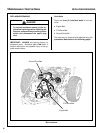
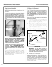
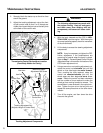
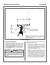
Control Rods
Control Arm
Transmission Control Rod and Arm Location
(Front Body Hidden for Clarity)
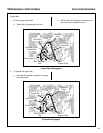
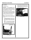
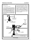
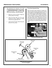
Control Rod
Locating Stud
Transmission
Control Arm
Tracking Adjustment Nut
(Adjusts Length of Control Rod)
Maximum Speed
Adjustment Set Screw
Ball Joint
Jam Nut
Tracking Adjustment Components
WARNING
The following adjustments are made with
the engine running. Keep all body parts
and tools away from rotating and hot
components, and secure all loose cloth-
ing.
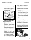
4. With the body lowered and the FSC in NEU-
TRAL-PARK, start the engine. With the engine
at normal operating speed, check for movement
of the drive wheels.
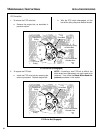
5. Lift the body to access the steering adjustment
components.
NOTE: It may be necessary to tighten the FSC
friction adjustment if the transmissions are
moved out of neutral when the body is raised.
Refer to Step 7 - Forward Speed Control Friction
Adjustment later in this section for location of the
FSC friction adjustment nut.
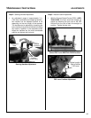
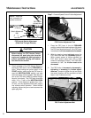
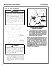
6. Using a wrench on one tracking adjustment nut,
rotate the control rod clockwise just until the
wheel on that side begins to move forward.
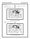
Then, counting the turns required, rotate the
control rod counterclockwise just until the
wheel stops and then begins to move in re-
verse. Rotate the control rod back clockwise
half the number of turns required to make the
wheel go from moving forward to reverse. The
transmission is now centered in the neutral win-
dow. Tighten the jam nut on the ball joint and
repeat the same procedure on the other trans-
mission.
7. Turn off the engine, and then lower the drive
tires onto the ground.