


Assembly Instructions
19
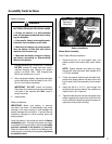
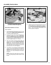
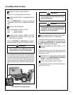
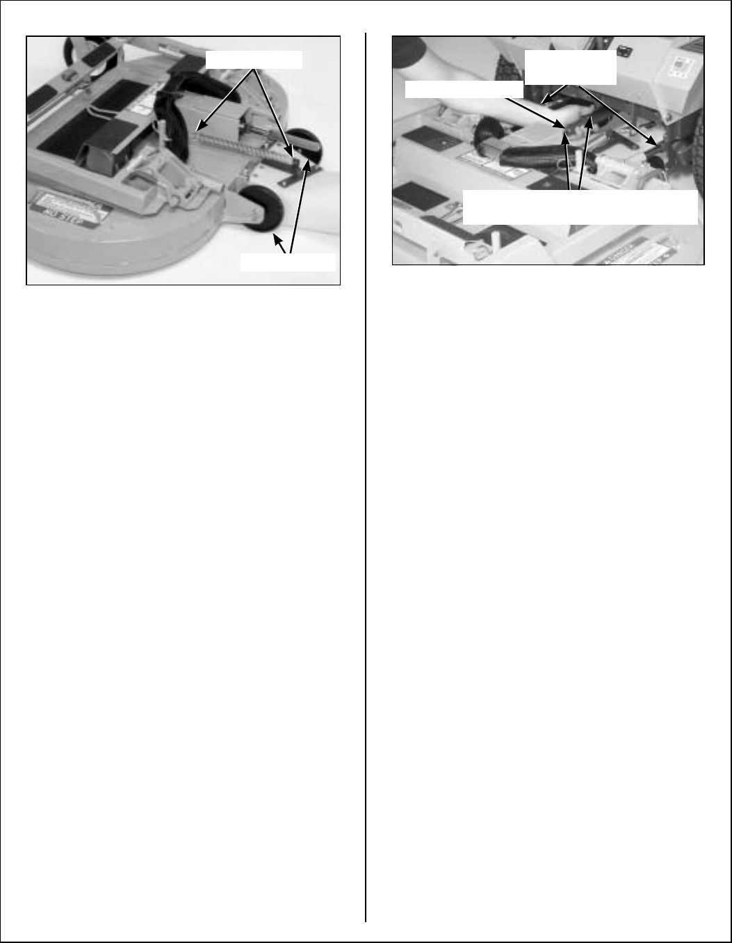
Tilt-Up Spring and Roller Wheel
Installation on Rear Discharge Deck
Mower Deck Installation on Tractor
Deck Installation
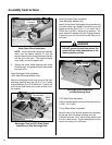
1. Lightly grease each deck support arm (2) on the
tractor. Refer to Mower Deck Installation photo
for location of deck support arm.
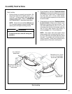
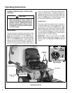
2. Engage the deck carrier frame tube sockets on
the tractor support arms (refer to Discharge
Chute and PTO Shaft Guard Installation photo
for socket location). Slide the deck onto the sup-
port arms approximately 3 in. (76 mm).
3. Align and connect the splined PTO shaft and
socket halves, as shown in Mower Deck Instal-
lation photo. The PTO shaft has a pilot end to
ease alignment of shaft; fit shaft end into socket
and rotate shaft until the splines line up as indi-
cated by arrows, then slide together.
4. If the deck is rear discharge (GHS equipped
model), the rear discharge chute will need to be
aligned and connected to the blower inlet during
the last 2 in. (51 mm) of slide action on the sup-
port arms.
NOTE: Raising the mower body may be help-
ful in fitting and guiding the deck chute into the
blower.
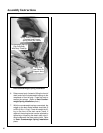
Mower Deck Installation/PTO Shaft Connection
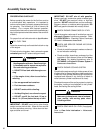
5. Install the hitch pin through the hole on the end
of each support arm to lock the deck in place (re-
fer to Deck Counterweight Spring Installation
photo). Two (2) hitch pins are included in the
owner’s packet of materials.
Attach Spring
Roller Wheels
Grease Deck
Support Arms
PTO Connection
Arrows on Shaft and Tube
(used to align when sliding together)