


Maintenance Instructions
62
REPLACING/REPAIRING/
ADJUSTMENTS
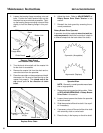
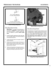
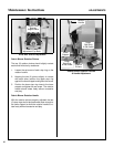
2. Loosen the three (3) nuts and three (3) bolts on
lower pulley bearing support and the adjust-
ment nut on the lower end of each (2) eyebolts
to release belt tension.
3. Loosen the two (2) set screws securing the up-
per pulley bearing to the shaft. Unbolt and re-
move the upper pulley bearing support.
4. Install the new drive belt and reinstall the upper
pulley bearing support. Secure the bearing on
the shaft by tightening the two set screws.
5. Adjust the belt tension. Refer to ADJUST-
MENTS of Debris Blower Drive Belt Tension
in this section. Tighten fasteners securely and
reinstall belt guard by reversing the removal
procedures.
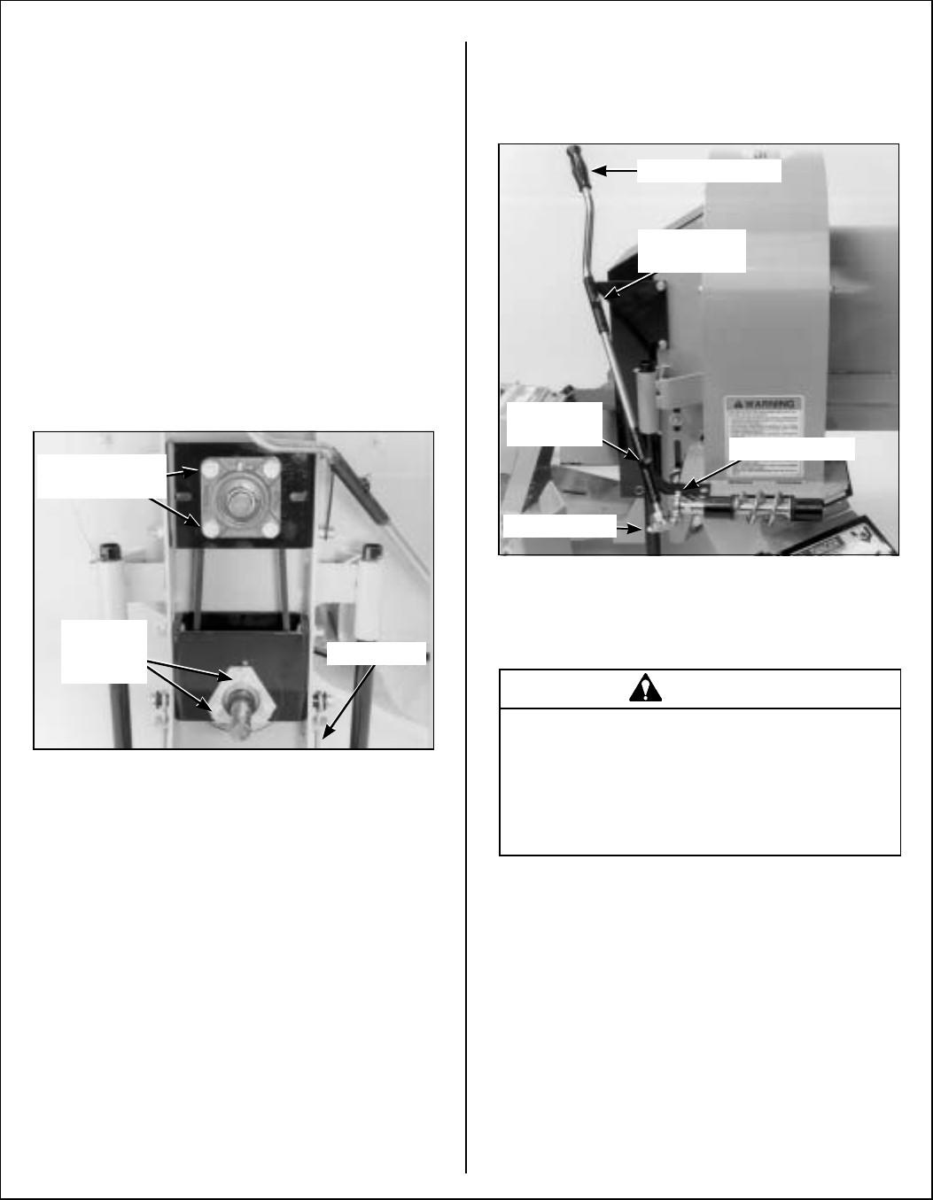
Debris Blower Drive Belt
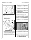
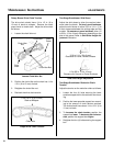
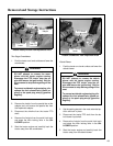
Debris Blower Rotation Pinions
1. Remove the drive pinion from the rotation han-
dle by loosening the set screw and pulling off
the pinion.
2. Remove the rotation handle lower stop ring and
pull up on the rotation handle. Loosen set screw
in upper stop ring. Pull rotation handle up out of
work way. Unbolt and remove the driven pinion.
3. Install the new driven pinion and tighten the nut
and bolt securely.
4. Lower the rotation handle back into its original
position and reinstall the lower stop ring. Posi-
tion the new drive pinion flush with the shaft and
securely tighten the pinion set screw.
5. Adjust the rotation pinions as instructed in AD-
JUSTMENTS of Debris Blower Rotation Pin-
ions in this section. Securely tighten the set
screw of each stop ring.
Debris Blower Rotation Pinions
ADJUSTMENTS
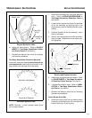
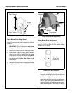
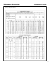
Dozer Blade Skid Shoes
Adjust the skid shoes to allow the required clear-
ance under the blade. On level, paved surfaces,
adjust the skid shoes to allow approximately 1/4 in.
(6 mm) clearance between the cutting edge and the
surface. On uneven or gravel surfaces, allow 1/2
to 3/4 in. (13 to 19 mm) clearance, depending on the
size of the gravel. Refer to Skid Shoe Height Ad-
justment illustration.
Eyebolt
Lower
Support
Bolts
Upper
Support Bolts
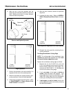
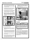
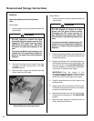
WARNING
DO NOT attempt to make any adjustments
with the tractor engine running. Disen-
gage the PTO clutch, stop the engine, and
remove the ignition key. Wait for all move-
ment to stop before getting off the seat.
Driven Pinion
Drive Pinion
Rotation Handle
Upper Stop
Ring
Lower
Stop Ring