


5
ASSEMBLY INSTRUCTIONS
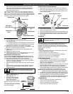
HANDLE ASSEMBLY
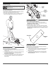
1. Remove the unit from the box.
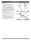
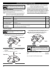
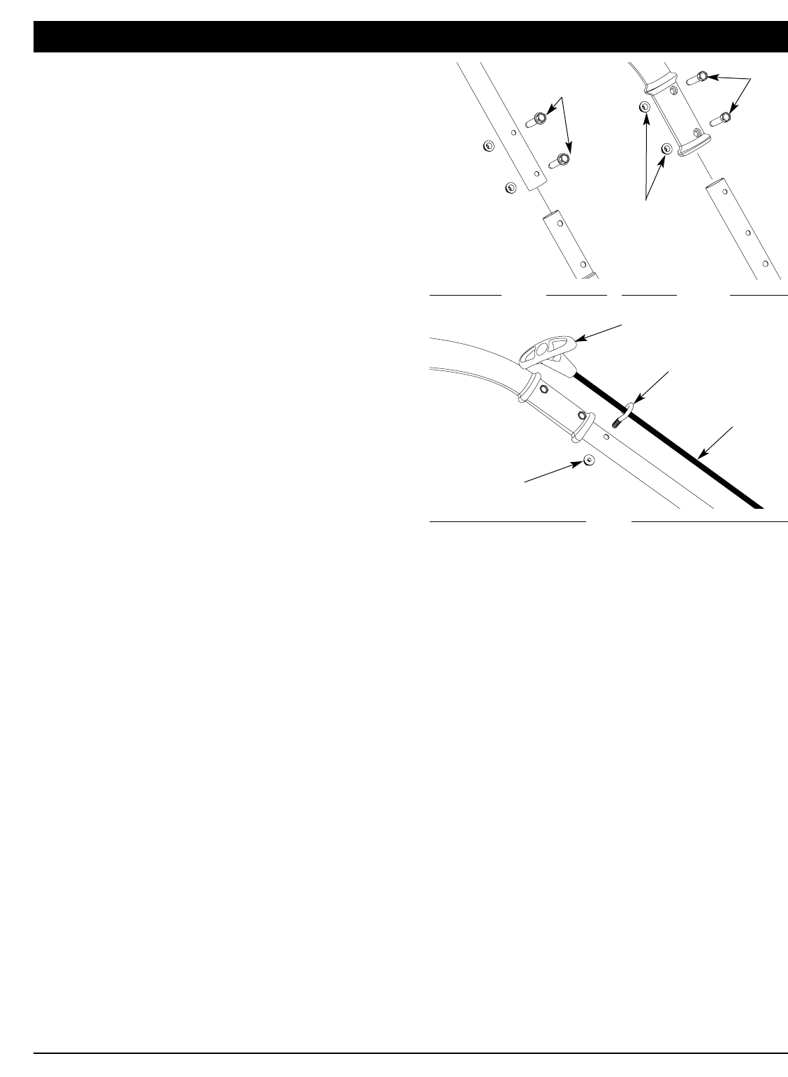
2. Place the 2-holed end of the straight metal shaft over the
shaft base on the unit and align the holes (Fig. 1).
3. Insert the two self-tapping screws (1/4” x 1-1/4”) into these
holes (Fig. 1).
4. Using a 3/8” wrench, screw each self-tapping screw into
the shaft until firm. DO NOT OVERTIGHTEN.
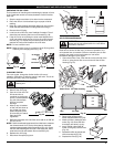
5. Insert the control handle onto the 3-holed end of the
straight metal shaft and align the control handle’s holes
with the two end holes of the straight metal shaft (Fig. 2).
NOTE: Because the control cables are pre-installed, care must
be taken when installing the control handle to not pinch or
bend the cables. This can damage them and cause them
to function improperly.
6. Insert the two screws (1/4” x 1-1/2”) into the recessed hex
holes on the handle (Fig. 2) and hold in place.
7. Hand-start the lock-nuts onto these bolts.
8. Using a 7/16” wrench, tighten each nut onto each bolt until
firm.
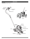
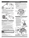
9. Pull out the starter rope and run it into the eye hook (Fig. 3).
10. Insert the eye hook into the remaining hole on the straight
metal shaft (Fig. 3).
11. Screw the nut onto the eye hook (Fig 3) and use a 7/16”
wrench to tighten. DO NOT OVERTIGHTEN.
12. Using the zip tie in the hardware bag, secure the handle
cables to the straight metal shaft mid-way between the eye
hook and the motor housing.
Fig. 1
Fig. 2
Self-Tapping
Screws
Bolts
Fig. 3
Eye Hook
Lock-Nuts
Lock-Nut
Starter Rope
Starter Rope Handle