


12 Section 3— ASSembly & Set-Up
Connecting the Battery Cables
CALIFORNIA PROPOSITION 65 WARNING!
Battery posts, terminals, and related accessories
contain lead and lead compounds, chemicals known
to the State of California to cause cancer and
reproductive harm. Wash hands after handling.
CAUTION: When attaching battery cables, always
connect the POSITIVE (Red) wire to its terminal first,
followed by the NEGATIVE (Black) wire.
For shipping reasons, both battery cables on your equipment may
have been left disconnected from the terminals at the factory. To
connect the battery cables, proceed as follows:
NOTE: The positive battery terminal is marked Pos. (+). The
negative battery terminal is marked Neg. (–).
NOTE: If the positive battery cable is already attached, skip
ahead to step 2.
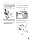
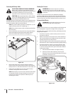
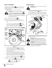
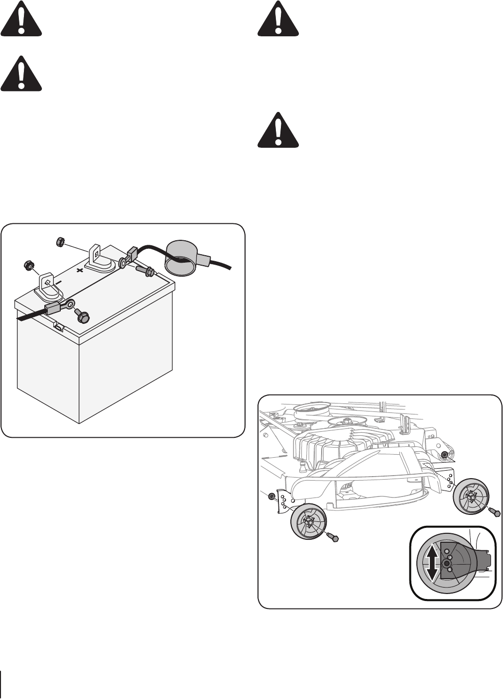
1. Remove the plastic cover, if present, from the positive battery
terminal and attach the red cable to the positive battery
terminal (+) with the bolt and hex nut. See Figure 3-9.
Figure 3-9
2. Remove the plastic cover, if present, from the negative
battery terminal and attach the black cable to the negative
battery terminal (–) with the bolt and hex nut. See Figure 3-9.
3. Position the red rubber boot over the positive battery
terminal to help protect it from corrosion.
NOTE: If the battery is put into service after the date shown
on top/side of battery, charge the battery as instructed
in the Service section your Operator’s Manual prior to
operating the tractor.
Checking Tire Pressure
WARNING! Maximum tire pressure under any
circumstances is 14 psi on rear tires and 14 psi on
front tires. Equal tire pressure should be maintained
at all times.
The tires on your tractor may be over-inflated for shipping
purposes. Reduce the tire pressure before operating the tractor.
Recommended operating tire pressure is 14 psi on rear tires and
14 psi on front tires. Check the sidewall of tire for maximum p.s.i.
Setting the Deck Wheels
WARNING!: Keep hands and feet away from the
discharge opening of the cutting deck.
NOTE: The deck wheels are an anti-scalp feature of the deck and
are not designed to support the weight of the cutting deck.
Move the tractor on a firm and level surface, preferably pavement,
and proceed as follows:
1. Check the tire pressure, make sure the pressure is correct
and equal on all tires.
2. Make sure the deck is level, both front-to-back and side-to-
side. See the Maintenance & Adjustments section for deck
leveling information and instructions.
3. Select the height position of the cutting deck by placing the
deck lift lever in the normally desired mowing height setting.
4. Check the wheels for contact or excessive clearance with
the surface below. The deck wheels should have between
¼” and ½” clearance above the ground. Proceed as follows
to adjust the wheels:
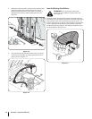
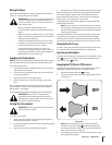
a. Raise the deck lift handle to its highest setting.
b. Remove the front deck wheels by removing the
flange lock nuts and shoulder bolts that secure them
to the deck. See Figure 3-10.
Figure 3-10