


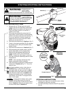

7
ASSEMBLY INSTRUCTIONS
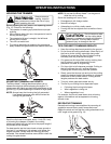
INSTALLING AND ADJUSTING THE D-HANDLE
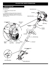
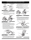
1. Remove the screws and bottom clamp piece that
were installed on the D-handle for shipping.
2. Place D-handle the over the shaft housing and onto
the bottom clamp (Fig. 1). Place it a minimum of 6
inches (15.24 cm) from the end of the shaft grip.
3. Start screws with a large Flat-head or T-25 Torx
screwdriver. Do not tighten until you make the handle
adjustment.
4. If the D-handle was pre-installed, loosen the screws
on the handle just enough to move it.
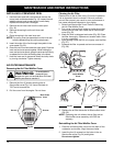
5. While holding the unit in the operating position
(Fig. 2), position the D-handle to the location that
provides you the best grip.
6. Tighten the clamp screws evenly, until the D-handle
is secure.
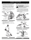
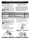
INSTALL THE CUTTING ATTACHMENT SHIELD
Use the following instructions if the cutting attachment
shield on your unit is not installed.
1. Place the cutting attachment shield onto the shaft
housing. Be sure the guard mounting bracket slides
into the slot on the edge of the cutting shield. Rotate
the shield into place, counterclockwise. The holes in
the guard mounting bracket and cutting attachment
shield will line up (Fig. 3).
2. From inside the cutting attachment shield, push the square
bolt through the hole until the threaded end protrudes
through the guard mounting bracket (Fig. 4).
Guard
Mounting
Bracket
Shaft Housing
Square Bolt
Cutting Attachment
Shield
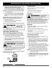
3. Put the washer on the bolt, then screw the wing nut
onto the bolt and tighten. Figure 5 shows the
installation process from underneath the unit.
Guard
Mounting
Bracket
Wing Nut
Cutting Attachment and Shield: Underside View
Cutting
Attachment
Shield
Wing Nut
Washer
Square Bolt
Washer
Hole
Fig. 3
Fig. 4
Fig. 5
Never operate the
trimmer without the
cutting attachment shield in place to
prevent serious personal injury.
WARNING:
Fig. 2
(4) Screws
Shaft
Housing
D-Handle
Bottom Clamp
Shaft Grip
Minimum 6 inches
(15.24 cm)
On/Off Stop Control
Fig. 1