


9
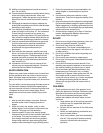
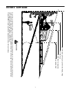
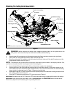
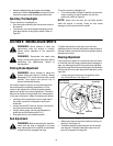
Attaching The Cutting Deck (Model R809K)
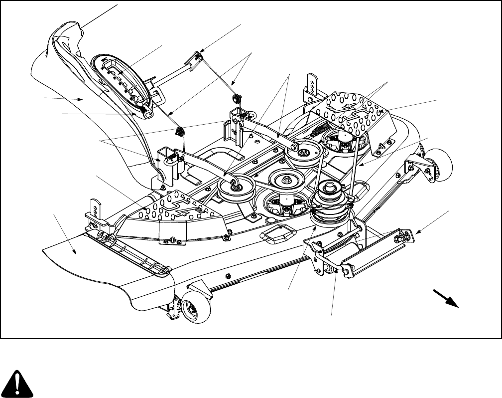
Figure 3
WARNING: Before attaching the cutting deck, engage the parking brake, turn the ignition key to the
OFF position and remove the key from the switch to avoid accidental starting.
• Raise the deck lift arms up and out of the way by placing the lift lever in the top notch on the right fender.
• Gently slide the cutting deck beneath the tractor from the right side.
• Move the cutting deck into position so that the hooks found on the front end of the deck fit snugly around the
deck stabilizer rod as shown in Figure 3.
NOTE: The stabilizer rod may be secured to the tractor frame with a plastic cable tie for shipping reasons. If so,
carefully cut the cable tie before mounting the front of the cutting deck.
• Lower the deck lift arms by placing the lift lever in the bottom notch on the right fender.
• Raise the left side of the cutting deck by grasping the deck and lifting upward. Pull the deck support pin (on
the left side of the deck) outward and align it with the hole on the rear of the left deck lift arm before releasing
the pin to lock it in place as shown in Figure 3. Repeat on the right side.
• Make certain that the PTO belt is routed around the spindle pulleys (found beneath the belt guards) and both
idler pulleys as illustrated in Figure 3.
• Route the PTO belt around the electric PTO clutch as shown in Figure 3.
IMPORTANT:
Be certain that the FLAT side of the PTO belt is the side coming in contact with the deck idler pulleys.
IMPORTANT:
After mounting the cutting deck, refer to Leveling the Deck in the ADJUSTMENTS section of this manual.
Perform any adjustments, if necessary, prior to operating the tractor
Deck Support Pins
Deck
Stabilizer
Bracket
Deck Stabilizer Rod
Deck Lift Arms
Electric PTO Clutch
Deck Idler Pulleys
Front of Tractor
NOTE:
Many tractor components not shown for clarity.
PTO / Deck Belt
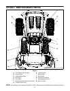
Deck Lift Assembly
Lift Lever
Notches
Fender
Lift Cables
Discharge Chute
Belt Guard
Belt Guard