Section 2: Assembly
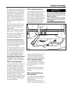
1. Remove the vinyl grip (B, Figure 2-6)
from the gear select lever (I). Place the
wood edge against the edge of the grip
and slowly pull off the grip.
2. Insert nylon bushing (Z, Figure 2-6)
up into console (L).
3. Slide spring and washers (J) down
onto gear select lever.
4. Insert gear select lever (I) up through
nylon bushing (Z) in handlebar console
(L). Guide pin (K) on gear select lever into
groove in shift quadrant (P).
5. Hold lower part of gear select lever (I,
Figure 2-7) against bracket (M). Position
retaining plate (N), removed earlier, as
shown in Figure 2-7 (plate below
bracket). Secure plate with two 1/4"-20 x
1/2" screws (O) and 1/4”-20 locknuts re-
moved earlier.
6. Slide grip (B, Figure 2-6) back onto
gear select lever (I).
7. Rotate gear select lever (I, Figures 2-
6 & 2-7) clockwise until spur (K - short
rod) on gear select rod stops in the neu-
tral position detent on the shift pattern
quadrant (Figure 2-6).
8. Move shift arm (X, Figure 2-7) from
side to side as necessary into each trans-
mission gear detent until transmission is
in neutral.
NOTE: Moving shift arm (X) all the way to
the left, and then one notch back to the
right, should put transmission into neu-
tral. When transmission is in neutral, unit
will move freely when pushed while hold-
ing the Operator Presence Control lever
(W, Figure 2-5) down. If transmission is
NOT in neutral, there will be a slight drag
on the wheels when pushing unit.
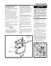
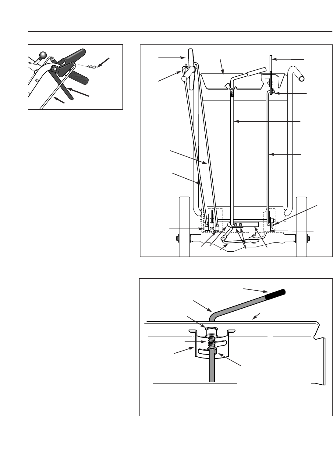
Figure 2-4A: Attach wheel drive control rod
to lever.
V
F
BB
Figure 2-5: Rear view of control rods.
G
N
P
O
H
F
E
I
C
J
AA
CC
D
L
M
V
W
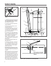
Figure 2-6: Detail – Gear Select Lever in Neutral (N) position.
I
L
K
P
B
Z
Pin (K) must be in this detent
when transmission neutral is
adjusted.
J
6


