


Section 2: Assembly
4. Raise handlebars to one of two height
settings and tighten the height adjustment
lever. Also, make sure all other mounting
hardware is securely tightened.
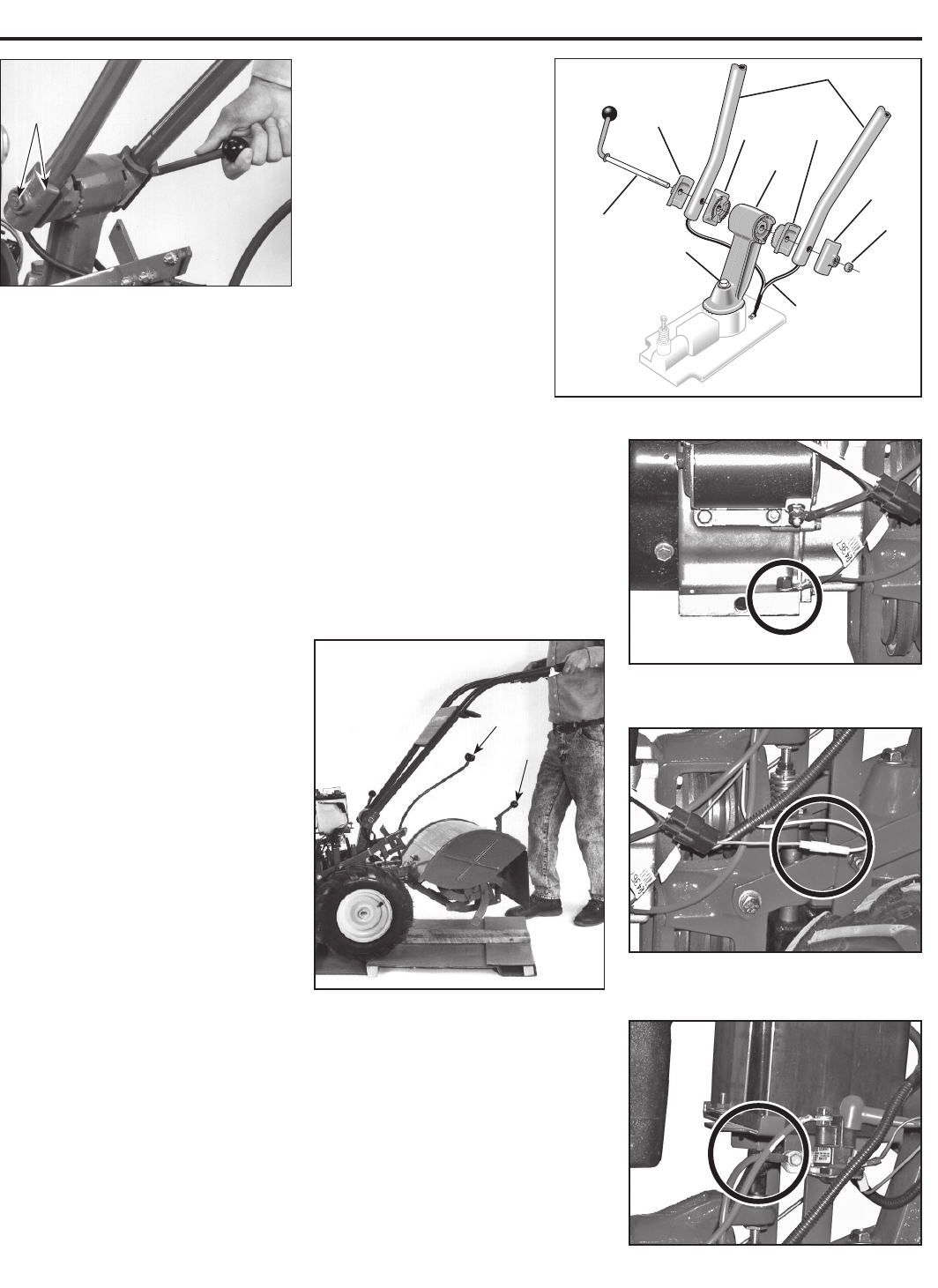
NOTE: Fully assembled handlebar
assembly should appear as shown in
Figure 2-3.
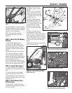
STEP 3: Move Tiller Off Shipping
Platform
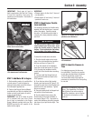
1. Set the Depth Regulator Lever
(A, Figure 2-4) to Travel position. Do
this by lifting the tiller by the handlebars,
then pulling straight back on the lever
and sliding down to the highest notched
setting.
2. Set the Wheel Speed Lever (B, Figure
2-4) to Freewheel position. To do this,
move the lever approximately halfway
between the Fast and Slow settings while
you rock the tiller forward and backward
until the wheels move freely.
3. Lift Handlebars high enough to clear
tiller tines and pull back firmly to dislodge
the tiller from the platform wheel wells.
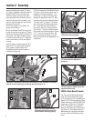
STEP 4: Connect Wire Harness
1. Ground green (and red for electric
start units) wire(s) to engine block, Figure
2-5A.
2. Connect the safety wire assembly
(green and yellow wires), Figure 2-5B.
3. Connect the tiller's main harness con-
nection to the neutral safety switch recep-
tacle, Figure 2-5C.
STEP 5: Attach Wheels/Tines/
PTO Drive Lever
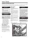
1. Loosen the bolt (Figure 2-2) on the
handlebar base and swing the handlebars
out to the right side.
2. Remove both sets of nuts,
star washers, screws, and one
bushing
(A, B, C, D, E, F, G, Figure 2-6)
from the yoke plates (H). There
is a bushing inside the short link
(I). Be careful not to lose it when
removing screw (G).
3. Slide the plates at the end
of the Wheels/Tines/PTO Lever
over the yoke plates (Figure 2-
9). To aid in the next step, insert
a screw temporarily into the
forward most holes (J, Figure
2-7) of the yoke plates and the
lever.
4. Align the rear most holes of
the yoke plates and the Wheels/
Tines/PTO Lever. Use long nose pliers to
hold the bushing (L, Figure 27) in place
while inserting the screw (K) through the
lever and yoke plates. Install star washer
(B, Figure 2-6) and nut (A), then hand
tighten.
5. Retrieve the clutch pawl spring (Figure
2-8) from hardware bag.
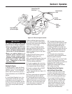
Figure 2-4: Photo shows the Depth
Regulator Lever (A) and the Wheel
Speed Lever (B).
B
A
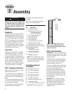
Figure 2-3. Fully assembled handle-
bars.
Left-Side
Clamp
and Nut
7
Figure 2-2. Handlebar assembly.
Left
Ratchet
Right
Ratchet
Handlebars
Right
Clamp
Left
Clamp
Height
Adjustment
Lever
Wire
Harness
Base
Bolt
Base
FRONT
OF TILLER
Nut
Figure 2-5A. Ground green (and red for
electric start units) wire(s) to engine block.
Figure 2-5B. Connect the safety wire
assembly (green and yellow wires)
Figure 2-5C. Connect the main harness
connection to the neutral safety switch.