


8 Section 3— ASSembly & Set-Up
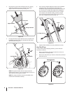
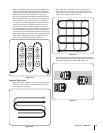
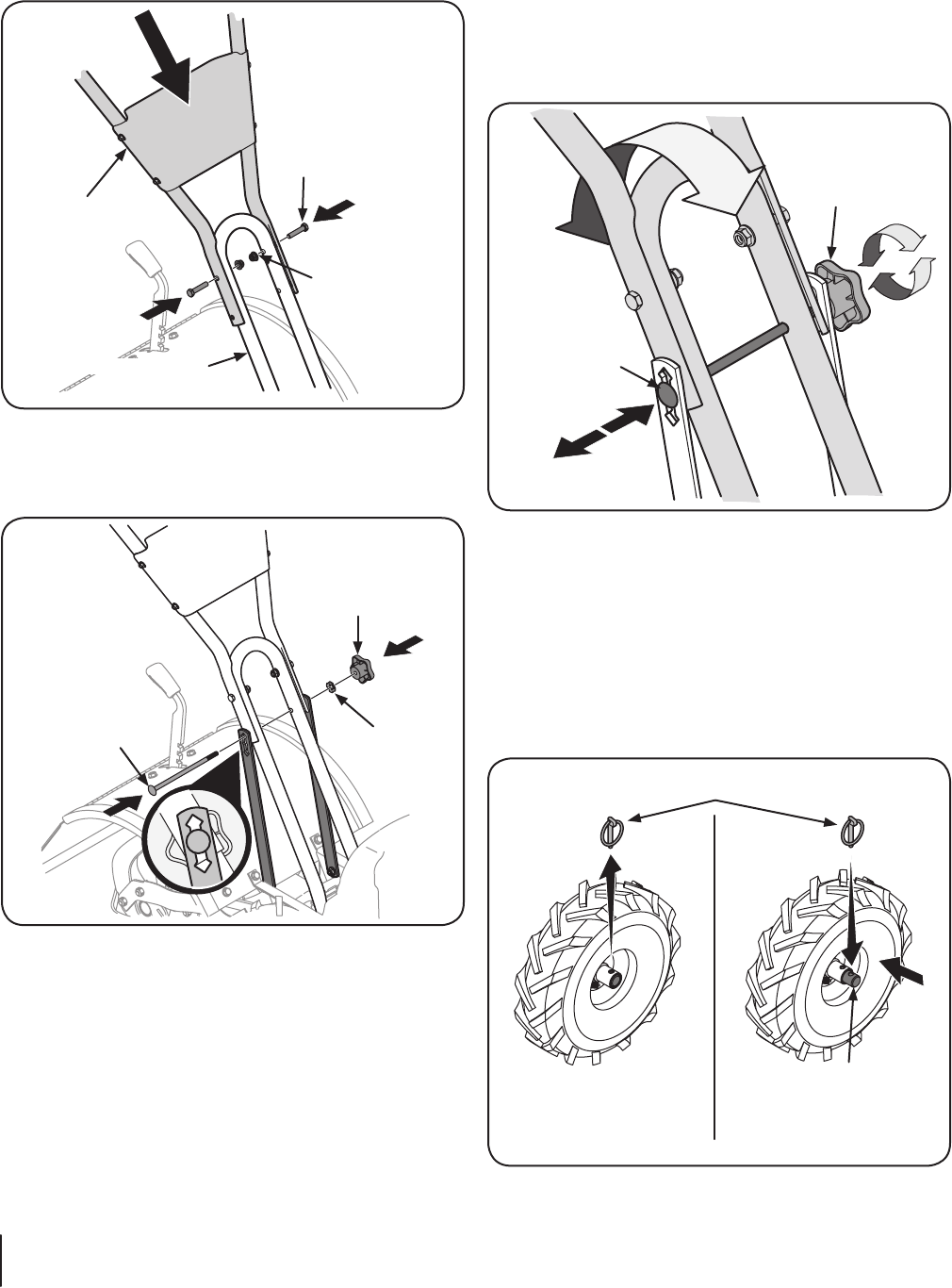
2. Using two hex screws and two flange lock nuts, loosely
attach the handlebar support using the upper holes.
Tighten the two screws securely. See Fig. 3-2.
Handle Support
Upper Handle
Hex Screw
Flange Lock Nut
Figure 3-2
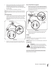
3. Loosely attach the support brackets to the outside of the
handlebar assembly using the carriage bolt, bell washer
and knob. Refer to Fig. 3-3.
Knob
Bell Washer
Carriage Bolt
Figure 3-3
NOTE: If a support bracket will not move, loosen the
attaching hex screws (⁄⁄-
NOTE: The support brackets must be assembled to the
outside of the handlebar assembly.
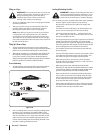
There are three height adjustment holes in the handlebar
support bracket. Use a setting that will position the
handlebars at approximately waist level when the tines are
loosen the knob on the handle, pull out on the carriage
screw, adjust to the desired setting, push the carriage
screw in until the square portion of the screw locks into
Knob
Carriage Screw
Figure 3-4
Tighten all the handlebar mounting hardware securely.
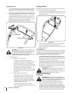
Move Tiller Off Crate
To roll the tiller off the shipping platform, put the wheels in
freewheel, as follows:
Place a sturdy block under the transmission to raise one
2. Remove the wheel drive pin from the wheel hub and wheel
shaft. See Fig. 3-5.
Wheel Drive Pin
Wheel Shaft
Figure 3-5