


22
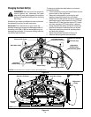
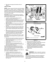
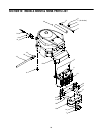
• Reroute the new upper drive belt as shown in
Figure 17.
Lower Drive Belt
NOTE: Proper removal of the lower drive belt requires
the removal of several tractor components. Read
through the following procedure prior to attempting it to
determine if you feel you could successfully complete it.
If you don’t, see an authorized Troy-Bilt Service Dealer
to have the belt changed.
IMPORTANT:
Note the routing of the lower drive belt
around both the pulleys and the belt keepers BEFORE
performing the following steps.
• Locate the variable-speed pulley through the
battery tray opening. See Figure 17.
• Remove the variable-speed pulley by loosening the
hex bolt that secures it to the transmission. Use a
second wrench to hold the hex nut on the bottom
side of the pulley.
• Slide the belt off of the variable-speed pulley as you
lift the pulley up and out through the battery tray
opening.
• Remove the rear idler pulley from the double- idler
bracket while unrouting the belt from around both
the rear and the front idler pulley. Refer to Figure
17.
• Remove the hex bolt from the center of the electric
PTO clutch and gently lower it off of the engine
crankshaft. Be careful not to lose any washers or
which may be found on top of the PTO clutch.
IMPORTANT:
When remounting the PTO clutch, torque
the center hex bolt to between 38 foot-pounds and 50
foot-pounds.
• Remove the drive belt by feeding it from both ends
toward the front idler pulley on the double-idler
bracket. See Figure 17.
• Reassemble by following the above steps in
reverse order.
• Reroute the new belt around the pulleys, belt
keepers and keeper pins EXACTLY as the old one
was routed. Refer to Figure 17.
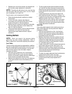
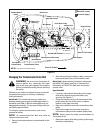
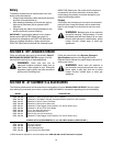
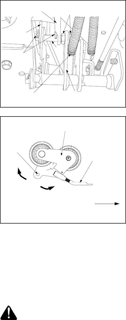
The drive pedal is properly adjusted when the hole
found in the double-idler bracket has approximately
1-3/8" of travel with ten pounds of pressure applied to
the drive pedal. See Figure 19.
Adjust the drive pedal after replacing the drive belts on
your tractor, if necessary, as follows:
• Locate the speed control assembly on the
underside of the steering support bracket. See
Figure 19.
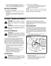
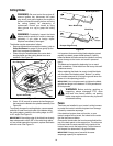
• Remove both hairpin clips from the pin which is
fastened to the speed control assembly (be careful
not to lose the small flat washers found on the pin).
See Figure 18.
Figure 18
Figure 19
• Remove the drive pedal return spring.
• Using two 9/16" wrenches, remove the pin from the
speed control assembly. See Figure 18.
• Thread the idler adjustment rod inward or outward
to lengthen or shorten the travel of the double-idler
bracket until proper adjustment is achieved.
• Reassemble by following the above steps in
reverse order.
Tires
WARNING: Never exceed the maximum
inflation pressure shown on the sidewall of the
tire.
Refer to the tire sidewall for exact tire manufacturer’s
recommended or maximum psi. Do not overinflate.
Uneven tire pressure could cause the cutting deck to
mow unevenly.
Speed Control
Assembly
Hairpin
Clips
Idler Adj. Rod
Pin
Drive Pedal
Return Spring
Place Wrenches Here
Neutral
Return
Bracket
Front of Tractor
NOTE: View shown from above tractor.
Double-idler Bracket
Idler
Adjuster Rod
Hole
1
-
3
/
8
”