


4
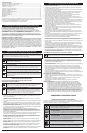
MAINTENANCE SCHEDULE
Perform these required maintenance procedures at the frequency stated in the table. These
procedures should also be a part of any seasonal tune-up.
NOTE: Some maintenance procedures may require special tools or skills. If you are unsure about
these procedures, take your unit to a Troy-Bilt or other qualifi ed service dealer.
NOTE: Maintenance, replacement, or repair of the emission control devices and system may be
performed by a Troy-Bilt or other qualifi ed service dealer.
NOTE: Please read the California/EPA statement that came with the unit for a complete listing of
terms and coverage for the emissions control devices, such as the spark arrestor, muffl er,
carburetor, etc.
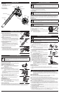
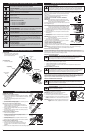
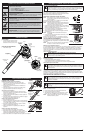
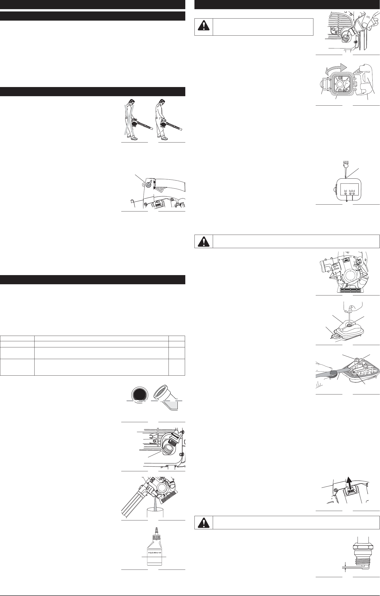
CHECKING THE OIL LEVEL
The importance of checking and maintaining the proper oil level in
the crankcase cannot be overemphasized. Check oil before each
use:
1. Stop the engine and allow oil to drain into the crankcase.
2. Place the engine on a level surface.
3. Clean the area around the oil plug before removing it. Keep
dirt, grass clippings, and other debris out of the engine.
4. Remove the oil plug (Fig. 14).
5. Look into the oil fi ll hole (use a fl ashlight if needed). The oil
should be just touching the innermost thread (Fig. 13).
6. If the oil level is not touching the innermost thread on the oil fi ll
hole, add a small amount of oil to the oil fi ll hole and recheck
(Fig. 13). Repeat this procedure until the oil level reaches the
innermost thread on the oil fi ll hole.
NOTE: Do not overfi ll the unit.
NOTE: Make sure the O-ring is in place on the oil plug when
checking and changing the oil (Fig. 14).
CHANGING THE OIL
Change the oil while the engine is still warm. The oil will fl ow freely
and carry away more impurities.
1. Remove the oil fi ll plug.
2. Pour the oil out of the oil fi ll hole and into a container by
tipping the unit to a vertical position (Fig. 15). Allow ample
time for complete drainage.
3. Wipe up any oil residue on the unit and clean up any oil that
may have spilled. Dispose of the oil according to federal, state
and local regulations.
4. Refi ll the crankcase with 2.03 fl .oz. (60 ml) of SAE 30 SF, SG,
SH oil (Fig. 17).
NOTE: Use the bottle and spout saved from initial use to
measure the correct amount of oil. The fi ll line on the
bottle’s label measures approximately 2.03 fl .oz. (60 ml)
(Fig. 16).
5. Check the level. See Checking the Oil Level.
6. Once full, replace the oil plug.
AIR FILTER MAINTENANCE
Cleaning the Air Filter
Failure to maintain the air fi lter will VOID the warranty.
1. To open the air fi lter cover, push the tab on the left side of the
cover inward and pull the air fi lter cover slightly out and to the
right (Fig. 18).
2. Remove the air fi lter (Fig. 18).
3. Wash the fi lter in detergent and water. Making sure to rinse the
fi lter thoroughly and allow it to dry.
4. Lightly coat the fi lter with clean SAE 30 motor oil.
5. Squeeze the fi lter to spread and remove excess oil.
6. Replace the fi lter.
NOTE: Operating the unit without the air fi lter will VOID the
warranty.
7. To reinstall the air fi lter cover, position the hooks on the right
side of the air fi
lter cover into the slots at the right side of the
back plate (Fig. 18).
8
. Swing the cover to the left and press closed so the air fi lter cover tab snaps into the slot on the
back plate (Fig. 18).
IDLE SPEED ADJUSTMENT
The idle speed of the engine is adjustable. An idle adjustment screw is between the air fi lter cover and
the engine starter housing (Fig. 19).
NOTE: Careless adjustments can seriously damage to the unit. A qualifi ed service dealer should
make carburetor adjustments.
If, after checking the fuel and cleaning the air fi lter, the engine still will not idle, adjust the idle speed
screw as follows:
1. Start the engine and warm up according to the Starting/
Stopping Instructions.
2. Release the trigger and let the engine idle. If the engine stops,
insert a small Phillips screwdriver in between the air fi lter cover
and the engine cover (Fig. 19). Turn the idle speed screw 1/8
of a turn clockwise at a time until the engine idles smoothly.
Checking the fuel, cleaning the air fi lter, and adjusting the idle
speed should solve most engine problems. If not and all of the
following are true:
• the engine will not idle
• the engine hesitates or stalls on acceleration
• there is a loss of engine power
take the unit to a qualifi ed service dealer.
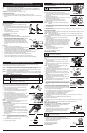
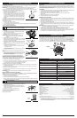
ROCKER ARM CLEARANCE
This requires disassembly of the engine. If you feel unsure or
unqualifi ed to perform this, take the unit to a qualifi ed service
dealer.
• The engine must be cold when checking or adjusting the
rocker arm clearance.
• This task should be performed inside, in a clean, dust free
area.
1. Remove the 8 engine cover screws with the appropriate tool
(Fig. 20), then remove the cover.
NOTE: Make sure to store the screws so that they can be
reinstalled into their original holes.
2. Disconnect the spark plug wire.
3. Clean dirt from around the spark plug and rocker arm cover.
Remove the spark plug from the cylinder by turning a 5/8 in.
socket counterclockwise.
4. Remove the screw holding the rocker arm cover with the
appropriate tool (Fig. 21). Remove the rocker arm cover and
gasket.
5. Turn the fl ywheel slowly to bring the piston to the top of its
travel (known as top dead center). Check that:
• The piston is at the top of its travel by looking in the spark
plug hole (Fig. 21)
• Both rocker arms move freely, and both valves are closed.
If these statements are not true, repeat this step.
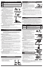
6. Slide the feeler gauge between the rocker arm and the valve
return spring. Measure the clearance between the valve stem
and rocker arm (Fig. 22). Measure both the intake and exhaust
valves.
The recommended clearance for both intake and exhaust is .003
– .006 in. (.076 – 0.152 mm). Use a standard automotive .005 in.
(0.127 mm) feeler gauge. The feeler gauge should slide between
the rocker arm and valve stem with a slight amount of resistance, without binding (Fig. 22.)
7. If the clearance is not within specifi cation:
a.
Turn the adjusting nut using a 5/16 inch (8 mm) wrench or nut driver (Fig. 22).
• To increase clearance, turn the adjusting nut counterclockwise.
• To decrease clearance, turn the adjusting nut clockwise.
b. Recheck both clearances, and adjust as necessary.
8. Reinstall the rocker arm cover using a new gasket (Fig. 21). Torque the screw to: 20–30 in•lb
(2.2–3.4 N•m).
9. Check the spark plug and reinstall. See Replacing the Spark Plug.
10. Reinstall the spark plug wire.
11. Reinstall the engine cover. Check alignment of the cover before tightening the screws. Tighten
screws.
NOTE: Make sure that the screws are reinstalled into their original holes (Fig. 20).
REPLACING THE SPARK PLUG
Use a replacement part number 753-05784 or Champion® spark
plug #RDZ4H. The correct spark gap is 0.025 in. (0.635 mm).
1. Stop the engine and allow it to cool.
2. Open the spark plug cover (Fig. 23).
3. Grasp the plug wire fi rmly and pull the cap from the spark plug.
4. Clean dirt from around the spark plug. Remove the spark
plug from the cylinder head by turning a 5/8 in. socket
counterclockwise.
5. Replace cracked, fouled or dirty spark plug. Set the spark gap
at 0.025 in. (0.635 mm) using a feeler gauge (Fig. 24).
6. Install a correctly-gapped spark plug in the cylinder head. Turn
the 5/8 in. socket clockwise until snug.
7. Reinstall the spark plug cover.
If using a torque wrench, torque to:
110-120 in.•lb. (12.3-13.5 N•m)
Do not over tighten.
Fig. 15
Fig. 17
Fig. 23
MAINTENANCE AND REPAIR INSTRUCTIONS
FREQUENCY MAINTENANCE REQUIRED SEE
Every 10 hours Clean and oil air fi lter p. 4
After 1st 10
hours
Change oil
Check rocker arm to valve clearance and adjust
p. 4
p. 4
Every 40 hours Change oil
Check rocker arm to valve clearance and adjust
Check spark plug condition and gap
p. 4
p. 4
p. 4
WARNING: To avoid serious personal injury,
always turn the unit off and allow it to cool before
cleaning or maintaining it.
WARNING: To avoid serious personal injury, always turn the unit off and allow it to cool
before cleaning or maintaining it.
Fig. 13
Oil Fill Line
Fig. 16
Fill Level
Fig. 19
Idle Adjustment
Screw
Fig. 22
Rocker Arm
Adjustment Nut
0.003–0.006 in.
(0.076–0.152 mm)
Feeler Gauge
Valve
Stem
Fig. 14
O-Ring
Oil Plug
Oil Fill Hole
Fig. 18
Air Filter Cover
Slot
Air Filter
Tab
Fig. 20
Screws
Screws
Fig. 21
Screw
Rocker
Arm
Cover
Spark
Plug
Hole
Fig. 24
0.025 in.
(0.635 mm)
WARNING: Do not sand blast, scrape or clean spark plug electrodes. Grit in the engine
could damage the cylinder.
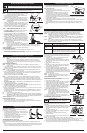
HOLDING THE BLOWER
Before operating the unit, stand in the operating position and
check for the following:
• The unit in the right hand and on the right side of the body. Do
not block the air intake which will affect the unit’s performance
(Fig. 11).
• If the conditions are dusty, the operator is wearing a dust
mask or face mask
• The unit is in good working condition
• The tubes are in place and secure
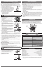
OPERATING TIPS
Using the Variable Speed Cruise Control
For longer periods of operation and to eliminate possible fi nger fatigue.
1. Move the variable speed cruise control toward the
FAST position to incrementally increase or maintain the unit’s
engine speed (Fig. 12). When the variable speed cruise
control is pressed, the trigger will recede into the handle.
2. To decrease engine speed, move the variable speed cruise
control to the SLOW position and the trigger will return to idle
(Fig. 12).
Other Tips
• Always use a fi rm grip when holding the unit.
• To reduce the risk of hearing loss, hearing protection is required.
• Operate power equipment only at reasonable hours
when people might not be disturbed. Comply with times listed in local ordinances. Usual
recommendations are 9:00 am to 5:00 pm, Monday through Saturday.
• To reduce noise levels, operate the unit at the lowest possible speed to do the job.
• Use rakes and brooms to loosen debris before blowing.
• Watch for bystanders, open windows or cars; blow debris safely away.
• Use the curved tube extension so the unit can work closer to the ground.
• Clean up after using blowers and other equipment. Dispose of debris appropriately.
OPERATING INSTRUCTIONS
Fig. 11
Fig. 12
Cruise
Control
FAST
SLOW
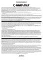
STARTING/STOPPING INSTRUCTIONS
IF USING THE OPTIONAL ELECTRIC STARTER OR POWER START BIT™ ACCESSORY
IF... the engine does not start, go back to step 3.
IF
... the engine fails to start after a few attempts, move the choke lever to Position 3 and
squeeze the throttle control. Press and hold the electric starter or drill ON (I) button for
2-second intervals until the unit starts.
IF WARM... If the engine is already warm, go back to step 7.
STOPPING INSTRUCTIONS
1. Release your hand from the trigger. Allow the engine to cool down by idling.
2. Press and hold the On/Off switch in the OFF (O) position until the unit comes to a complete stop
(Fig. 8).
MAINTENANCE AND REPAIR INSTRUCTIONS