


10
WARNING: Before
operating your machine,
carefully read and understand
all safety, controls and
operating instructions in this
Manual, the separate Engine
Owner’s Manual, and on the
decals on the machine.
Failure to follow these
instructions can result in
serious personal injury.
INTRODUCTION
This Section describes the location and
function of the controls on your tiller. Re-
fer to the following Section, Operation for
detailed operating instructions.
Practice using these controls, with the en-
gine shut off, until you understand the op-
eration of the controls and feel confident
with each of them.
ENGINE CONTROLS
Refer to the engine manufacturer’s Engine
Owner’s Manual (included in the tiller liter-
ature package) to identify the controls on
your engine.
IMPORTANT: The control for stopping the
engine is located on the engine.
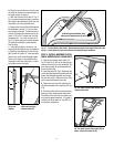
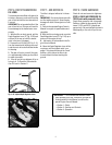
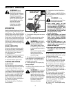
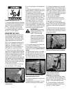
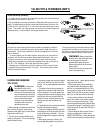
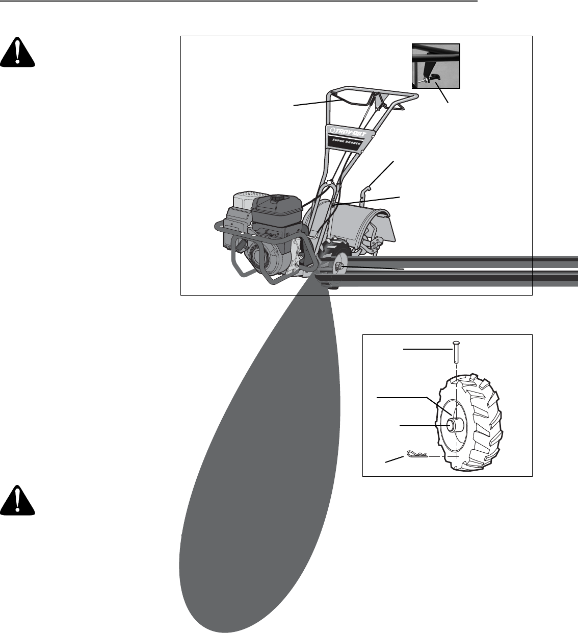
WHEEL DRIVE PINS
Each wheel is equipped with a wheel drive
pin (A, Figures 3-2 and 3-3) that secures
the wheel to the wheel shaft (B). The
wheels can be positioned in either a
WHEEL DRIVE or a FREEWHEEL mode.
WARNING: Never allow
either of the wheels to be in the
FREEWHEEL position when the
engine is running. Always put
both wheels in the WHEEL
DRIVE position before starting
the engine.
Failure to comply could cause
loss of tiller control, property
damage, or personal injury.
Before starting the engine, put both wheels
in the WHEEL DRIVE position by inserting
the wheel drive pins through the wheel
hubs and the wheel shaft. Doing so
“locks” the wheels to the wheel shaft,
causing the wheels to turn when either the
Forward Clutch Bail (all models) or the Re-
verse Clutch Control (Models 634F and
634A) is engaged.
Use the FREEWHEEL mode only when the
engine is not running. In FREEWHEEL, the
wheel drive pins are placed only through
the holes in the wheel shaft (not the wheel
hubs), thus allowing the wheels to turn
freely when you manually move the tiller.
To place the wheels in WHEEL DRIVE or
FREEWHEEL:
1. Stop engine, disconnect spark plug wire
from spark plug and allow engine to cool.
WARNING: Do not place
tiller on its side when changing
wheel drive positions. Doing so
could result in gasoline leaking
from the fuel tank.
Failure to follow this instruction
could result in personal injury
or property damage.
2. Raise one wheel about one inch off the
ground and place a sturdy support under
the transmission.
3. Remove hairpin cotter (C, Figures 3-2
and 3-3) from wheel drive pin (A).
4. FOR WHEEL DRIVE MODE (Figure 3-2):
Slide wheel outward and align holes in
wheel hub (D, Figure 3-2) and wheel
shaft (B). Insert wheel drive pin (A)
through wheel hub (D) and wheel
shaft (B). Secure wheel drive pin with hair-
pin cotter (C) by pushing hairpin cotter in
as far as it will go. Repeat with the other
wheel and then remove the support from
beneath the transmission.
5. FOR FREEWHEEL MODE ( Figure 3-3):
Slide the wheel inward and insert the wheel
drive pin (A, Figure 3-3) only through the
hole in the wheel shaft (B). Secure wheel
drive pin with hairpin cotter (C) by pushing
hairpin cotter in as far as it will go. Repeat
for the other wheel and then remove the
support from beneath the transmission.
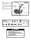
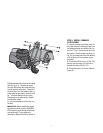
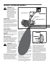
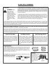
Forward Clutch Bail
Depth Regulator
Handlebar Height Adjustment
Reverse Clutch Control
(Models 634F/634A)
Wheel Drive Pin
(on each wheel)
Figure 3-2: WHEEL DRIVE position.
A
D
B
C
SECTION 3: FEATURES AND CONTROLS
Figure 3-1: Tiller features and controls. See seperate Engine Owner’s Manual to identify
engine controls.