


Features and Controls
3
Section
8
INTRODUCTION
This Section describes the location and
function of the features and controls on
your machine. Refer to Section 4: “Opera-
tion” for detailed operating instructions.
IMPORTANT: Refer to the separate engine
manual for detailed information about the
controls on the engine.
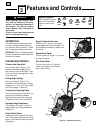
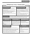
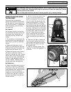
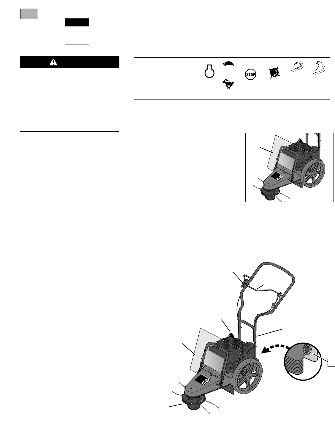
FEATURES AND CONTROLS
Trimmer Head Control Bail
Pull the control bail (A, Figure 3-1) up
against the handlebar (engage bail) to
start rotation of the trimmer head. Let go
of the control bail (disengage bail) to stop
the trimmer head.
Cutting Height Settings
The trimmer head (B, Figure 3-1) is
adjustable to an infinite number of height
settings from 1-1/2" to 4-1/2" (see “Adjust
Line Cutting Height” in Section 4).
Trimming Line Mounting Plates
The two trimming lines (C, Figure 3-1) are
secured to wire-looped line holders.
Replacing the trimmer lines is easy (see
“Changing Trimmer Lines” in Section 5).
Handlebar Height Adjustment
The handlebar (D, Figure 3-1) has two
height settings (see “Adjust Handlebars”
in Section 4).
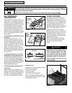
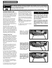
Plastic Debris Shield
A heavy-duty plastic shield (E, Figures 3-1
and 3-1A) prevents debris build-up on the
engine. The shield tilts forward for access
to the engine.
Engine Throttle Control Lever
Use this lever (F, Figure 3-1) to change
engine speeds and to stop the engine. The
throttle settings are shown on a decal next
to the lever.
Engine Recoil Starter
The recoil starter (G, Figure 3-1) is used to
pull start the engine.
Fuel Primer Button
The fuel primer button (H, Figure 3-1)
allows a cold engine to be primed for
faster, easier starting.
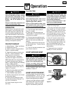
Before operating your machine, care-
fully read and understand all safety,
controls and operating instructions in
this Manual, the separate Engine
Owner’s Manual, and on the decals on
the machine.
Failure to follow these instructions can
result in serious personal injury.
WARNING
Operating Symbols
Various symbols (shown
here, with word descrip-
tions) are used on the
unit.
STOP
ENGINE
STOP
TRIMMER
HEAD
ENGAGE
BAIL
DISEN-
GAGE
BAIL
SLOW
FAST
STOP
WARNING
T
H
R
O
W
N
O
B
J
E
C
T
H
A
Z
A
R
D
O
b
j
e
c
t
s
s
u
c
h
a
s
r
o
c
k
s
,
p
e
b
b
l
e
s
a
n
d
s
m
a
l
l
d
e
b
r
i
s
w
i
l
l
b
e
t
h
r
o
w
n
v
i
o
l
e
n
t
l
y
b
y
t
h
e
c
u
t
t
i
n
g
h
e
a
d
,
r
e
s
u
l
t
i
n
g
i
n
s
i
g
n
i
f
i
c
a
n
t
h
a
z
a
r
d
t
o
e
y
e
s
a
n
d
e
x
p
o
s
e
d
b
o
d
y
p
a
r
t
s
!
K
e
e
p
c
h
i
l
d
r
e
n
,
p
e
t
s
a
n
d
b
y
s
t
a
n
d
e
r
s
5
0
f
e
e
t
a
w
a
y
f
r
o
m
m
a
c
h
i
n
e
w
h
i
l
e
o
p
e
r
a
t
i
n
g
.
B
e
a
l
e
r
t
t
o
h
i
d
d
e
n
o
b
s
t
a
c
l
e
s
.
R
O
T
A
T
I
N
G
C
U
T
T
I
N
G
H
E
A
D
D
o
n
o
t
s
e
r
v
i
c
e
o
r
a
d
j
u
s
t
c
u
t
t
i
n
g
h
e
a
d
o
r
o
t
h
e
r
m
o
v
i
n
g
p
a
r
t
s
u
n
l
e
s
s
e
n
g
i
n
e
i
s
s
t
o
p
p
e
d
a
n
d
s
p
a
r
k
p
l
u
g
w
i
r
e
i
s
d
i
s
c
o
n
n
e
c
t
e
d
.
1904403 (1/97)
•
•
•
Figure 3-1: Features and controls
A
C
C
D
B
G
E
F
H
W
A
R
N
IN
G
T
H
R
O
W
N
O
B
J
E
C
T
H
A
Z
A
R
D
O
b
j
e
c
t
s
s
u
c
h
a
s
r
o
c
k
s
,
p
e
b
b
l
e
s
a
n
d
s
m
a
l
l
d
e
b
r
i
s
w
i
l
l
b
e
t
h
r
o
w
n
v
i
o
l
e
n
t
l
y
b
y
t
h
e
c
u
t
t
i
n
g
h
e
a
d
,
r
e
s
u
l
t
i
n
g
i
n
s
i
g
n
i
f
i
c
a
n
t
h
a
z
a
r
d
t
o
e
y
e
s
a
n
d
e
x
p
o
s
e
d
b
o
d
y
p
a
r
t
s
!
K
e
e
p
c
h
i
l
d
r
e
n
,
p
e
t
s
a
n
d
b
y
s
t
a
n
d
e
r
s
5
0
f
e
e
t
a
w
a
y
f
r
o
m
m
a
c
h
i
n
e
w
h
i
l
e
o
p
e
r
a
t
i
n
g
.
B
e
a
l
e
r
t
t
o
h
i
d
d
e
n
o
b
s
t
a
c
l
e
s
.
R
O
T
A
T
I
N
G
C
U
T
T
I
N
G
H
E
A
D
D
o
n
o
t
s
e
r
v
i
c
e
o
r
a
d
j
u
s
t
c
u
t
t
i
n
g
h
e
a
d
o
r
o
t
h
e
r
m
o
v
i
n
g
p
a
r
t
s
u
n
l
e
s
s
e
n
g
i
n
e
i
s
s
t
o
p
p
e
d
a
n
d
s
p
a
r
k
p
l
u
g
w
i
r
e
i
s
d
i
s
c
o
n
n
e
c
t
e
d
.
1904403 (1/97)
•
•
•
Figure 3-1A: Debris shield in operating
position.
E