


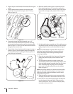
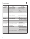

Slip the auger control belt (the front belt) off the engine 2.
pulley.
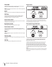
Pull the 3. brake bracket assembly towards the cable
guide roller and unhook the auger cable “Z” fitting.
Refer to Figure 7-5.
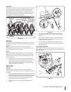
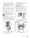
From both sides of the frame assembly, use a 1/2" 4.
wrench to remove the three hex tap screws securing
the transmission frame to the auger housing assembly.
Refer to Figure 7-1. NOTE: Do not remove the lower hex
flange lock nut on each side.
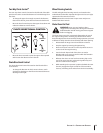
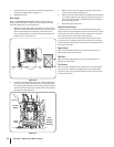
Place a block of wood underneath the auger housing as 5.
shown in Figure 7-6 and separate auger housing from
the transmission frame by tilting the housing forward
and pulling up the handles.
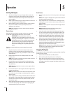
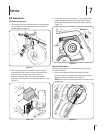
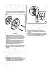
Block the impeller with a piece of wood the prevent 6.
from spinning and use a 1/2” wrench to remove the
hex screw and flat washer from the center of the auger
input shaft and auger pulley adapter. Refer to Figure
7-7.
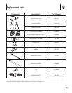
Lift the brake bracket assembly out of the pulley groove 7.
and slide the pulley assembly off the posts of the auger
pulley adapter to remove the old belt. Refer to Figure
7-7.
NOTE: The pulley adapter may slide off the auger input
shaft when removing the pulley. Use extra caution to
ensure the adapter does fall and get damaged when
removing the pulley.
Place the new auger belt in the V-groove of the auger 7.
pulley and place the pulley w/belt inside the belt
keepers.
Turn the pulley as necessary to align its three slots 8.
approximately with the posts of the pulley adapter, then
move the brake bracket assembly away from the input
shaft. While aligning the pulley slots and adapter
posts, push the auger pulley fully onto the adapter.
Refer to Figure 7-7.
NOTE: If the pulley adapter was removed with the pulley,
align the splines of the pulley adapter and auger input
shaft, and push the pulley and adapter onto the input
shaft. Refer to Figure 7-7.
Slide the washer onto the hex screw removed earlier 9.
and apply Loctite 262 to the threads of the hex screw.
Insert the hex screw through the pulley assembly and 10.
into the threads of the input shaft. Torque the hex
screw to 250-325 in. /lbs. to secure the auger pulley
assembly on the input shaft.
Figure 7-7
Figure 7-6
Figure 7-5
A
C
B
Adapter Post
Pulley Slot
Belt Keeper
20 se c t i O n 7— se r v i c e