


Assembly & Set-Up
3
7
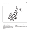
Assembly
References to the right and left side of tiller are determined from
behind the equipment in the operating position.
Recommended Tools for Assembly
⁄” open-end wrench
⁄” open-end wrench
Clean oil funnel
specifications and quantity required.
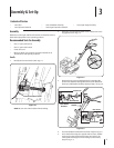
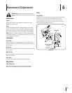
Handle
Forward Clutch Cable
Figure 3-1
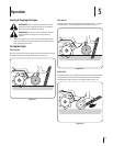
NOTE: Be sure not to kink cables while attaching.
2. Hook the “Z” end of the forward clutch cable into the tine
engagement lever Fig. 3–2.
Figure 3-2
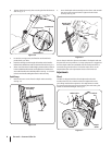
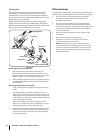
3. Remove the hex screw and bell washer from the right side
of the frame. Hold the cable guide bracket on the left side of
2
1
3
Hex Screw
Hex Screw
Bell Washer
Bell Washer
Cable Guide
Bracket
Handle
Figure 3-3
Insert the handle into tiller frame as shown. Step 2 in Fig. 3–3.
5. Insert the bolt through the cupped washer, frame, handle
and into the cable guide bracket (note the notch in the
cable guide bracket goes over the flange on the frame.)
Step 3 in Fig. 3–3.
Contents of Carton