


11
Maintenance
Engine
Refer to the separate engine manual for all engine
maintenance instructions.
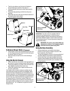
• Check engine oil level before each use as
instructed in the separate engine manual packed
with your unit. Read and follow instructions
carefully.
• Clean air cleaner every 25 hours under normal
conditions or once a season. Clean every few hours
under extremely dusty conditions. To service the air
cleaner, refer to the separate engine manual
packed with your unit.
• The spark plug should be cleaned and the gap
reset once a season. Check engine manual for
correct plug type and gap specifications.
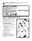
Removing The Flail Screen
If the discharge area becomes clogged, remove the flail
screen and clean area as follows:
• Stop the engine and make certain the Yard
Vacuum has come to a complete stop.
• Disconnect spark plug wire from spark plug and
ground against the engine.
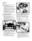
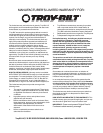
• Remove the bag or blower chute (if equipped) from
the unit as instructed in the OPERATION section to
obtain access to flail screen. See Figure 11.
Figure 11
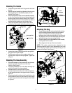
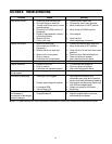
• Remove self-tapping screw on right side of unit that
attaches to the fail screen. It may be necessary to
remove the hose bracket hanger to get access to
the hex screw. See Figure 12.
• Remove hex screw on top of rear housing mounting
bracket and the flange lock nut that secures flail
screen. See Figure 11.
• Remove and clean the screen by scraping or
washing with water. Reinstall the flail screen.
Figure 12
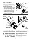
Sharpening Or Replacing Chipper Blade
Because the engine on this unit has a tapered
crankshaft, a special impeller tool (part number 753-
0900) is required to remove the impeller assembly. For
further assistance, contact your local service dealer.
NOTE: When tipping the unit, empty the fuel tank and
keep spark plug side up.
• Disconnect the spark plug wire and ground it away
from the spark plug.
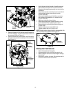
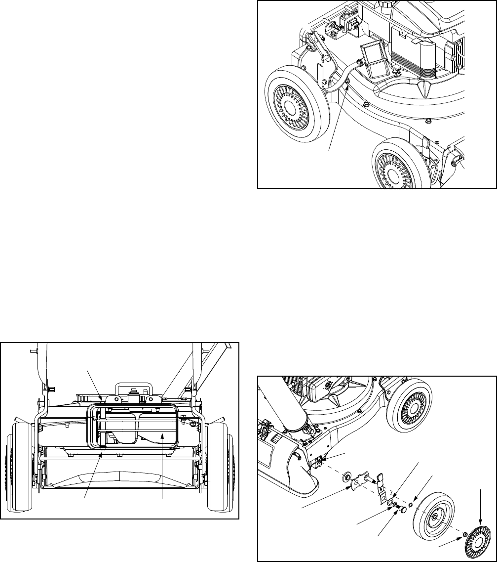
• Remove the front hubcaps, flange lock nuts, front
wheels, and wave washers that attach to the pivot
arm assemblies. See Figure 13.
Figure 13
• Remove the shoulder screws, thrust and bell
washers that go through the pivot arms to the front
support brace. The front support brace and lock nut
can be removed at this time as well.
• Remove the three screws on the upper housing
that secure the nozzle cover and the nine screws
that secure the lower housing to the upper housing.
See Figure 14.
Hex Screw &
Flat Washer
Flail Screen
Lock Nut
Remove
Self-Tapping
Screw
Hubcap
Flange Lock Nut
Wave Washer
Shoulder
Screw
Bell Washer
Pivot Arm Assembly
Thrust Washer
Front Support
Brace & Lock Nut