


6
3
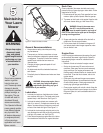
Setup and
Adjustment
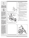
1. Remove any packing material which may be between
upper and lower handles.
a. Pull up and back on upper handle as shown in
Figure 3-1. Make certain the lower handle is seated
securely into the handle mounting brackets. Do not
crimp cable while lifting the handle up.
b. Tighten star knobs to secure upper handle to
lower handle. Make sure that each carriage bolt is
seated properly in the handle.
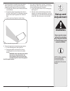
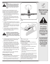
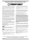
2. Locate the hairpin clip on the weld pin on each side of
lower handle.
a. Remove hairpin clip from this hole. Using a pair
of pliers, insert hairpin clip into the hole on pin
closest to the bracket. See Figure 3-2. Repeat on
other side.
b. Insert a carriage bolt from the hardware pack into
the upper hole on the handle mounting bracket.
Secure with one plastic wing nut, also included
in the hardware pack. Repeat on other side with
remaining items from hardware pack.
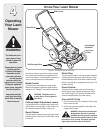
3. The rope guide is attached to the right side of the
upper handle. See Figure 3-3. Loosen the wing nut
which secures the rope guide.
a. Hold blade control against upper handle.
b. Pull starter rope out of the engine. Release blade
control.
c. Slip starter rope into rope guide.
d. Tighten wing nut.
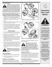
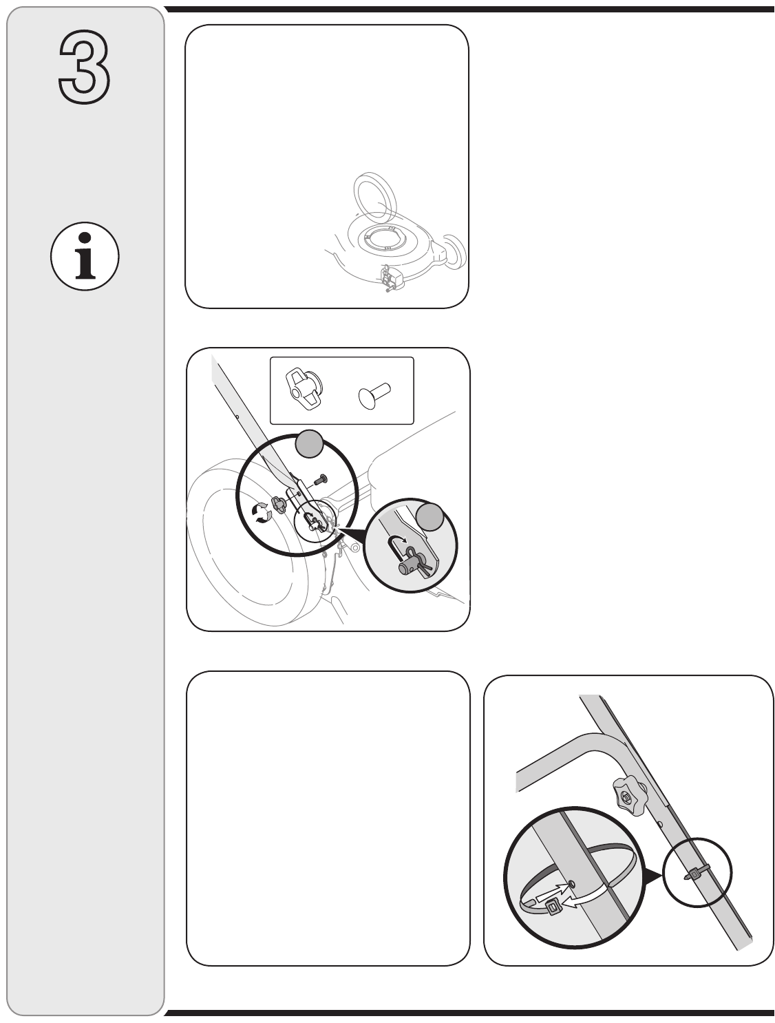
4. Insert post on cable tie into hole provided on the lower
handle. Pull cable tie tight and trim excess. See Figure
3-4.
Stand behind the mower
as if you were going to
operate it. Your right
hand corresponds to the
right side of the mower;
your left hand corre-
sponds to the left side of
the mower.
Figure 3-1: Unfold handle, tighten hardware.
IMPORTANT
This unit is shipped with-
out gasoline or oil in the
engine. Fill up gasoline
and oil as instructed in
the accompanying engine
manual BEFORE operat-
ing your mower.
Make sure to route cable
outside the lower handle.
Do not crimp cable while
lifting the handle up.
Figure 3-2: Secure lower handle to mounting brackets.
Wing Nuts (2)
Hardware Pack
Carriage Bolts (2)
Figure 3-3: Pull recoil starter through rope guide and tighten. Figure 3-4: Secure cables to handle using cable tie.
This Operator’s Manual
may cover a range of
product specifications
for various models.
Characteristics, features,
and engines discussed
and/or illustrated in
this manual may not be
applicable to all models.
MTD LLC reserves the
right to change product
specifications, designs,
and equipment without
notice and without incur-
ring obligation.
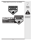
A
B