


7
ASSEMBLY
IMPORTANT: Read entire operator’s manual before you
attempt to assemble or operate your new pressure washer.
If you have any questions with the assembly of your pressure
washer, please call the pressure washer helpline at
1-888-611-6708. If calling for assistance, please have the
model, revision, and serial number from the data tag available.
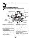
See “Know Your Pressure Washer” for data tag location.
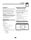
Remove Pressure Washer from
Carton
• Remove the parts bag packed with pressure washer.
• Slice two corners at the end of carton from top to
bottom so the panel can be folded down flat, then
remove all packing material.
• Roll pressure washer out of carton.
Carton Contents
Items in the carton include:
• Main Unit
• Safety Goggles
• Handle
• Plastic Accessory Tray
• High Pressure Hose
• Spray Gun
• Nozzle Extension with Quick Connect Fitting
• Oil Bottle
• Parts Bag (which includes the following):
• Operator’s Manual
• Engine Operator’s Manual
• Owner’s Registration Card
• Bag containing 4 multi–colored Quick Connect Spray
Tips
• Handle Fastening Hardware Kit (which includes):
• Carriage Bolt
• “L” Bolt (2)
• Plastic Knobs (3)
• Tree Clips (4)
PREPARING PRESSURE
WASHER FOR USE
If you have any problems with the assembly of your
pressure washer or if parts are missing or damaged, call the
pressure washer helpline at 1-888-611-6708.
To prepare your pressure washer for operation, you
will need to perform these tasks:
1. Fill out and send in registration card.
2. Attach handle to main unit, then attach accessory tray
to handle.
3. Add oil to engine crankcase.
4. Add fuel to fuel tank.
5. Connect high pressure hose to spray gun and pump.
6. Connect water supply to pump.
7. Attach nozzle extension to spray gun.
8. Select/attach quick connect spray tip to nozzle
extension.
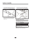
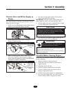
Attach Handle and Accessory Tray
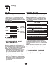
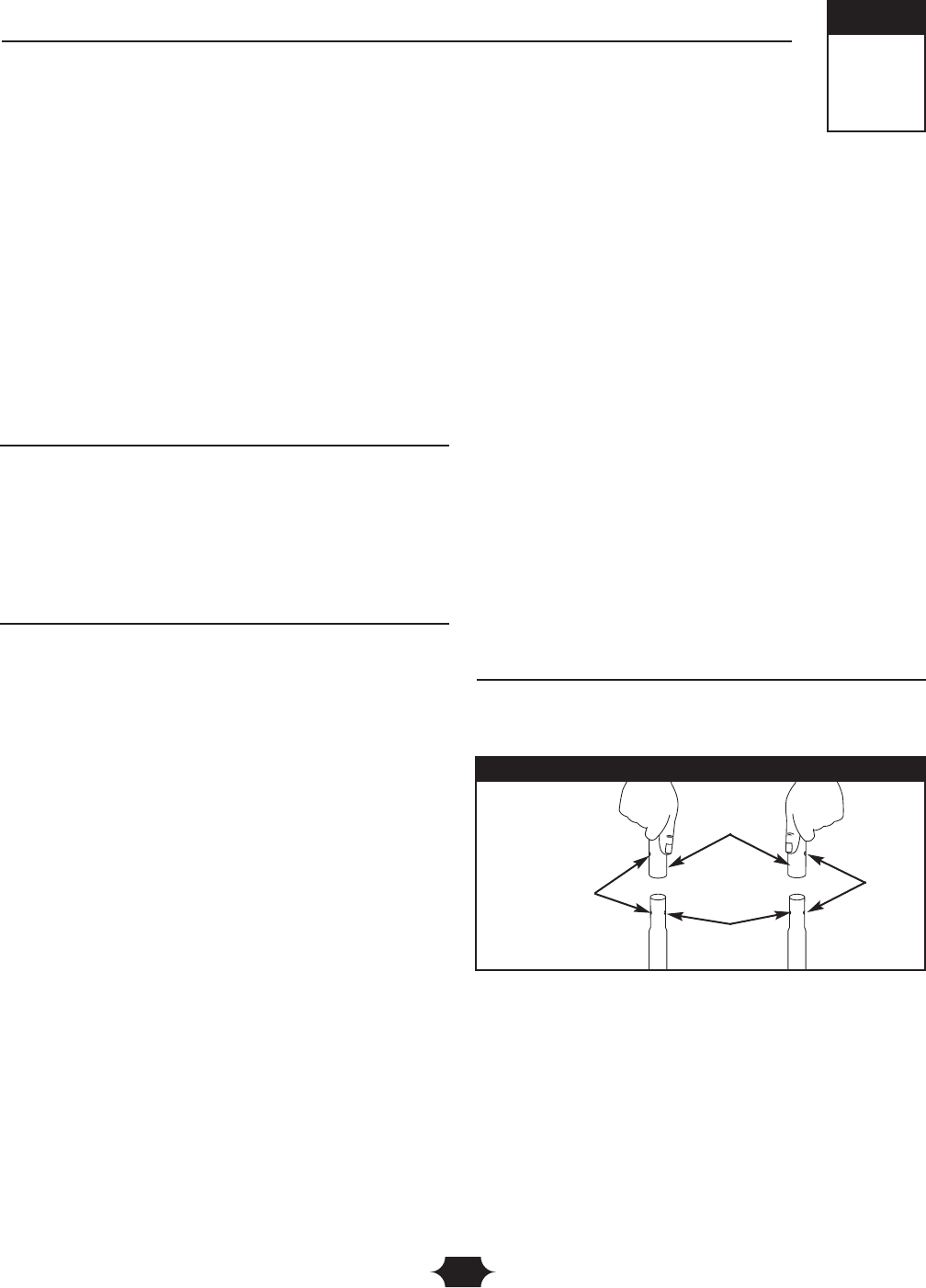
1. Place handle onto handle supports connected to main
unit. Make sure holes in handle align with holes on
handle supports (Figure 1).
NOTE: It may be necessary to move the handle supports
from side to side in order to align the handle so it will slide
over the handle supports.
3
Section
Assembly
Align Holes
Handle
Handle
Supports
Figure 1 — Attach Handle to Base