


74 BCXC-SVX01B-EN
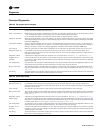
Diagnostics
Diagnostics
Translating Multiple Diagnostics
The controller senses and records each diagnostic independently of other diagnostics. It is possible
to have multiple diagnostics present simultaneously. The diagnostics are reported in the order they
occur.
Possible diagnostics include:
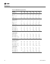
Table 39. Tracer ZN010 and ZN510 test sequence for 1-heat/1-cool configurations
Steps
Fan Cool output
(a)
(a)At the beginning of step 2, the controller attempts to clear all diagnostics.
Heat output Damper
J1-1, J1-3 J1- J1- J1-
1. Off Off Off Off Closed
2. Fan high High Off Off Closed
3. Exhaust fan
(b)
(b)Tracer™ ZN010 and ZN510 have a binary output default as “none” on J1-X from the factory. If the unit has a 2-speed fan,
step 3 will energize the low fan speed. If the unit has a single speed fan, step 3 will continue to energize the high fan speed.
This binary output can be reconfigured as an exhaust fan, with the use of Rover™ software.
Off Off Closed
4. Fan Low Off Off Closed
5. Cool High On Off Closed
6. Heat High Off On Closed
7. Two-position damper
(c)
(c) After the fresh air damper step, the test sequence performs the exit step.This initiates a reset and attempts to return the
controller to normal operation.
High Off Off Open
8. Exit
(d)
(d)For all 1-heat/1-cool applications including 2-pipe changeover, the cooling and heat test stage energize. This occurs even
though during normal 2-pipe changeover operation binary output controls the unit valve for both cooling and heating.
Note: The 2-position damper energizes during this step if the controller is configured for a 2-position damper.
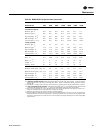
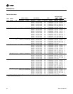
Table 40. Tracer ZN520 test sequence
Step
Fan
Main
valve
Electric heat or
aux. valve
Fresh air
damper Generic/baseboard heat
J1-1 J1-2 J1-3 J1-5 J1-6 J1-9 J1-10 J1-11 J1-12 TB4-1
1. Off
(a)
Off Off Off Off On
EH: off
Off aux: on Off On Off
2. Fan high
(b)
High Off Off Off Off Off Off Off Off Off
3.
(c)
Off Off Off Off Off Off Off Off Off
4. Fan low Off Off Low Off Off Off Off Off Off Off
5. Main open High Off Off On Off Off Off Off Off Off
6. Main close, EH1 on High Off Off Off On On Off Off Off Off
7. Aux. open High
EH1 on
Exh
(d)
Off Off Off On Off Off Off Off
8. Aux. close, damper open High Off Off Off Off Off
EH1 off
On
EH2 on
On Off Off
9. Damper close High Off Off Off Off Off Off Off On Off
10. Generic/baseboard heat energized High Off Off Off Off Off Off Off Off On
11. Exit
(e)
Exit
(a)Upon entering manual output test mode, the controller turns off all fan and electric heat outputs and drives.
(b)At the beginning of step 2, the controller attempts to clear all diagnostics.
(c) The low fan speed output energizes at step 3. If the unit is configured for a 1 speed fan, the fan remains on high speed at step 3.
(d)If the unit is configured for a 1- or 2-speed fan, and BOP2 is configured for an exhaust fan, the exhaust fan output energizes on step 7. The exhaust
fan output is shared with medium speed.
(e)After step 10, the test sequence performs an exit. This initiates a reset and attempts to return the controller to normal operation.