


Installation Procedure ___________________________________________________
To assure maximum performance from your 800S series sprinklers, read these instructions
completely prior to installation or service.
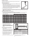
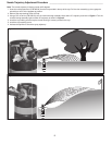
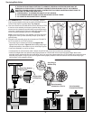
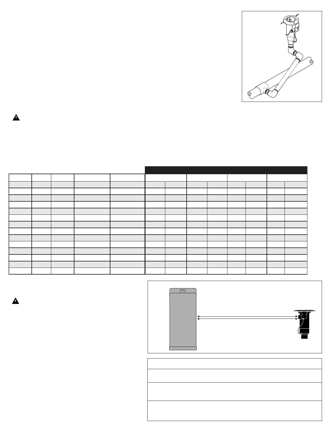
Constructing Swing Joints
1. Construct or provide triple swing joints for each sprinkler as shown in Figure 1. Use PVC or
ABS pipe nipple for the sprinkler connection.
Note: On sites where the possibility of heavy equipment rolling over a sprinkler exists, the
swing joint will flex preventing damage to the lateral or main lines. On a new installation in
raw ground where the sprinklers are to be initially installed above the finished grade and
lowered when new turf is established, the swing joint allows sprinkler repositioning without
changing risers. This is a common and practical procedure which eliminates the problem of
dirt being accidentally introduced into the lateral lines when a riser is changed.
2. Flush lines thoroughly prior to installing sprinkler.
3. Apply PTFE tape on riser threads (not required on ACME threads). Install sprinkler to riser and tighten.
CAUTION: Use only PTFE tape on riser threads. Use of pipe dope or other types of sealing compounds can cause
deterioration of sprinkler body threads.
Connecting Control Wires (Electric Models Only)
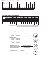
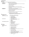
1. Route control wires to sprinklers. Provide extra wire at sprinkler to allow for height adjustment. One common wire and station
wire is required for each sprinkler. See Wire Sizing Chart, Table 1 for proper application.
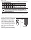
Note: Wire length data provided in Table 1 is the sum of the station and common wire legs. See example in Figure 2.
2. Attach control wires to solenoid leads using an
approved waterproof splicing method.
CAUTION: All wire splices and field
connections must be waterproofed to prevent
short circuit to ground and subsequent controller
damage.
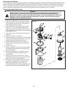
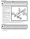
Connecting Hydraulic Control Tubing
1. Route control tubing from the controller to the
sprinkler location(s).
Note: Leave an 18" (45.7 cm) service loop of tubing
at each sprinkler to facilitate movement of sprinkler
and service operations. Refer to Table 2 for tubing
run length and sprinkler elevation information.
2. Flush tubing thoroughly to remove all air and debris.
3. Remove the tube retainer and poly cap from the
tubing adapter at the base of the sprinkler.
4. Slide the tube retainer over the end of the control
tubing and attach tubing to adapter.
5. Slide tube retainer over adapter area to secure tubing.
3
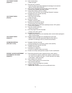
Table 2: Hydraulic Control Systems
Maximum Distance
Type of System* From Controller Elevation Restrictions
Normally Open (01) Valve elevation should not exceed
with 3/16" Control Tubing 500' 25' ABOVE controller elevation or
70' BELOW controller elevation.
Normally Open (01) Valve elevation should not exceed
with 1/4" Control Tubing 1000' 25' ABOVE controller elevation or
70' BELOW controller elevation
Voltage AWG mm
2
Voltage Drop
Circular Mils 1 Sprinkler
Total Wire Length Between Controller and Sprinkler
2 Sprinklers3 Sprinklers 4 Sprinklers
23
14/14
2.5/2.5
2.5/4.0
2.5/5.5
4.0/4.0
4.0/5.5
4.0/7.0
5.5/5.5
2.5/2.5
2.5/4.0
2.5/5.5
4.0/4.0
4.0/5.5
4.0/5.5
4 4100 3285' 1001 m
1298 m
1770 m
1595 m
2067 m
2812 m
2540 m
1251 m
1622 m
2213 m
1993 m
2584 m
3515 m
3175 m
500 m
649 m
885 m
797 m
1033 m
1406 m
1270 m
626 m
811 m
1106 m
996 m
1292 m
1757 m
158
7 m
334 m
432 m
590 m
531 m
689 m
937 m
846 m
417 m
541 m
738 m
664 m
861 m
1172 m
1058 m
250 m
324 m
443 m
399 m
517 m
703 m
635 m
313 m
406 m
553 m
498 m
646 m
879 m
790 m
1642' 1095' 821'
23
14/12
45315
4259' 2129' 1419' 1064'
23
14/10
4 7250
5809' 2904' 1936' 1452'
23
12/12
46530
5232' 2616' 1744' 1308'
23
12/10
4 8465
6783' 3391' 2261' 1695'
23
12/8
4 11515
9227' 4613' 3075'
2306'
23
10/10
4 10400
8333' 4166' 2778'
2083'
24 14/14 5 4100 4106' 2053' 1369' 1026'
24 14/12 5 5315
5323'
2662' 1774'
1331'
24 14/10 5 7250 7261' 3631'
2420'
1815'
24
12/12
56530 6540' 3270' 2180' 1635'
24
12/10
5 8465 8478' 4239' 2826'
2119'
24
12/8
5 11515 11533'
5766'
3844'
2883'
24
10/10 10/10
5 10400 10416' 5208' 3472' 2604'
Table 1: Wire Sizing Chart
*
- All hydraulic connections on Toro valves are
1
⁄4" insert type.
- Control line pressure must be equal to or greater than mainline pressure.
- Control line pressure range is 40 to 150 PSI.
A U
T O
O
N
O
F F
Figure 1
Figure 2
Station Wire = 1095' (334m)
Common Wire = 1095' (334m)
Total Wire Length = 2190' (668m)