


VALVE WON'T OPEN (a) Plugged controller discharge line or discharge port in pilot valve.
(Hydraulic) – Verify by checking for discharge at discharge line when station is
activated. If no discharge, refer to Controller Service Manual.
SPRINKLER WEEPING (a) Damaged or blocked valve seat.
(Slow leak in valve) – Remove blockage and, if necessary, replace valve assembly.
(b) Damaged piston seal or piston assembly.
– Replace valve assembly.
(c) Low pressure on supply line .
– Check for low pressure reason and correct.
(d) Elevation of normally closed sprinkler exceeds 75' (22.9 m) differential.
SEVERAL VALVES ON DIFFERENT (a) Control tubing leak which lowers supply pressure to other stations.
STATIONS FAIL TO CLOSE – Turn controller from station to station until a station is reached where
(Hydraulic) only valves on that station stay open. The leak would be in the tubing
on that station. Isolate and repair.
(b) Leak in supply line to controller.
– Verify by checking pressure in all control lines.
(c) Leak in controller pilot valve.
– Verify by constant discharge from controller.
(d) Plugged supply line filter.
– Replace filter if more than 3 psi (0.21 bar) differential exists.
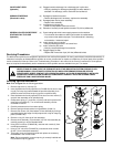
Servicing Procedures ____________________________________________________
The 800S series sprinklers are designed to provide the user trouble-free operation for many years without scheduled maintenance. If
it becomes necessary to disassemble the sprinkler to correct a malfunction or replace a component, all internal parts of the sprinkler
can be accessed from the top. Refer to the Troubleshooting Procedure in this manual in the event of a malfunction. Some special
tools are required for disassembly and/or maintenance of the sprinkler and are available from your Toro dealer.
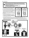
Servicing Sprinkler Mechanism
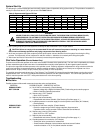
Note: Refer to Figure 3 for the following procedure.
1. Remove cap screw (1) and cap (3).
2. Insert hooked end of multi-purpose tool (P/N 995-83) into slot in snap
ring (8). Pull snap ring inward toward the sprinkler assembly, then
upward to remove from the snap ring groove in sprinkler body.
3. Insert hooked end of multi-purpose tool into slot over inner nozzle (7)
and pull riser assembly out of sprinkler body.
4. Grasp return spring (11) and riser (13) firmly and hold in place while
removing nozzle base (5). Turn nozzle base assembly counter-
clockwise to remove.
5. Carefully release tension from return spring.
6. Remove spring and seal retainer/o-ring assembly (9 and 10).
7. Remove rock screen (16) from bottom of riser assembly by turning it
counterclockwise with edge of multi-purpose tool or tips of snap ring
pliers (P/N 995-100).
8. Remove o-ring (12) from top of riser assembly.
9. Remove drive assembly (14) and stator (15) from riser assembly by
carefully pressing on end of threaded shaft.
10. Using a 5/8" nut driver (P/N 995-99), unscrew main nozzle (4) from
nozzle base assembly.
11. Using a 7/16" nut driver (P/N 995-79), unscrew two inner nozzles
(6 and 7) from nozzle base assembly.
12. Thoroughly clean and inspect all parts and replace as necessary.
Reassemble in the reverse order.
Note: During reassembly, ensure snap ring is correctly installed and
fully seated in snap ring groove.
6
1
2
3
5
4
6
7
8
9
10
12
13
14
11
15
16
Figure 3
WARNING
NEVER STAND OR LEAN OVER THE SPRINKLER WHILE THE IRRIGATION SYSTEM IS BEING FILLED,
DURING MANUAL OR AUTOMATIC OPERATION OR WHEN PERFORMING SPRINKLER SERVICE
PROCEDURES. DIRECT CONTACT WITH IRRIGATION SPRAY, A FAILED OR IMPROPERLY INSTALLED
SPRINKLER CONNECTION OR SPRINKLER COMPONENTS FORCIBLY EJECTED UPWARD UNDER
PRESSURE CAN CAUSE SERIOUS INJURY.