


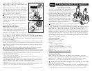
• Model 53707 Installation (Figure 1)
Step 1- Cut a 4" length of 1" schedule 40 PVC pipe for each valve.
Step 2-Using PVC primer and cement, assemble the pipe section to the valve inlet
and tee fitting, aligning the tee perpendicular to the valve. Repeat this procedure for
each valve in the manifold.
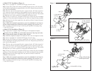
Note: The last valve in the manifold can be connected with a 90° elbow instead of
a tee. However, if future expansion of the sprinkler system is expected, use the tee
fitting and a 4" section of 1" schedule 40 PVC pipe capped on the end. This enables
the main line to be easily connected to additional downstream valves.
Step 3- Using 4" sections of 1" schedule 40 PVC pipe, connect the valve assemblies
together to create the manifold, making sure the valves are aligned during assembly.
Step 4- Ensure the end of the supply line is dry and free of burrs. Cement the mani-
fold to the main line.
Step 5- Allow the cemented connections to cure for a minimum of one hour (or
per the cement manufacturer’s directions) before applying water pressure. If no
leaks occur after pressurization, begin connecting the sprinkler zone piping using
1" class 200 PVC pipe.
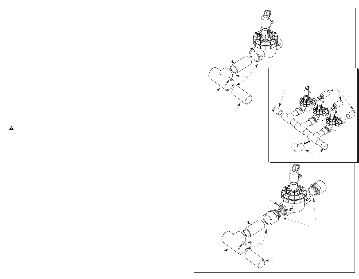
• Model 53709 Installation (Figure 2)
Step 1- Apply three complete wraps of PTFE tape to the slip/thread adapters.
Caution: Use only PTFE tape on threaded connections. Pipe dope and other
types of pipe thread sealants can damage plastic threads.
Step 2- Install a slip/thread adapter into each end of the valve and tighten securely.
Step 3- Cut a 4" length of 1" schedule 40 PVC pipe for each valve.
Step 4- Using PVC primer and cement, assemble the valve and PVC components as
shown, aligning the tee fitting perpendicular to the valve. Repeat this procedure for
each valve in the manifold.
Note: The last valve in the manifold can be connected with a 90° elbow instead of
a tee. However, if future expansion of the sprinkler system is expected, use the tee
fitting and a 4" section of 1" schedule 40 PVC pipe capped on the end. This enables
the main line to be easily connected to additional downstream valves.
Step 5- Using 4" sections of 1" schedule 40 PVC pipe, connect the valve assemblies
together to create the manifold, making sure the valves are aligned during assembly.
Step 6- Ensure the end of the supply line is dry and free of burrs. Cement the
manifold to the main line.
Step 7- Allow the cemented connections to cure for a minimum of one hour (or
per the cement manufacturer’s directions) before applying water pressure. If no
leaks occur after pressurization, begin connecting the sprinkler zone piping using
1" class 200 PVC pipe.
Cement
Joints
Cement
Joints
1" Slip x Thread Adapter
(PTFE-Taped threads)
1" Slip x Slip x
Slip PVC Tee
1" Slip x Slip x
Slip PVC Tee
1" Sch 40 PVC
4" Long
1" Sch 40 PVC 4" Long
Valve Inlet
1" Sch 40 PVC
4" Long
1" Sch 40 PVC
4" Long
Valve Inlet
Figure 2
Figure 1
90° Elbow or Tee and Cap Plug
1" Sch 40 PVC
Water Supply Pipe
Valve Manifold Assembly
1" Class 200 PVC
Pipe To Sprinklers