


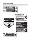
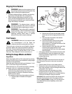
11
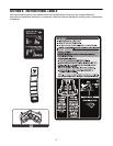
Shipping Brace Removal
WARNING: Make sure the engine is off, set
the parking brake and remove the ignition key
before removing the shipping brace
.
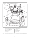
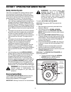
• Locate the shipping brace, if present, and warning
tag found on the right side of the cutting deck.
• While holding the discharge chute with your left
hand, remove the shipping brace with your right
hand by grasping it between your thumb and index
finger and rotating it clockwise.
WARNING: The shipping brace, used for
packaging purposes only, must be removed
and discarded before operating your tractor.
WARNING: The mowing deck is capable of
throwing objects. Failure to operate the tractor
without the discharge cover in the proper
operating position could result in serious
personal injury and/or property damage.
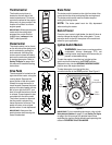
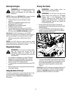
Tire Pressure
WARNING: Maximum tire pressure under
any circumstances is 30 psi. Equal tire
pressure should be maintained at all times.
The tires on your unit may be over-inflated for shipping
purposes. Reduce the tire pressure before operating
the tractor. Recommended operating tire pressure is
approximately 10 p.s.i for the rear tires & 14 p.s.i. for the
front tires. Check sidewall of tire for maximum p.s.i.
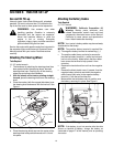
Setting the Gauge Wheels and Roller
Gauge Wheels
Select the height position of the cutting deck by placing
the deck lift lever in any of the six different cutting height
notches on the right fender.
Adjust the deck wheels so that they are between ¼-inch
and ½-inch above the ground as follows.
Place the tractor on a firm and level surface, preferably
pavement, refer to d., and proceed as follows:
• Place the tractor’s deck lift handle in the normally
desired mowing height setting, then check the
gauge wheels for contact or excessive clearance
with the surface below.
• If the wheels contact the surface adjust as follows:
a. Raise the deck lift handle to its highest
setting.
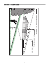
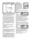
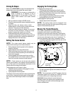
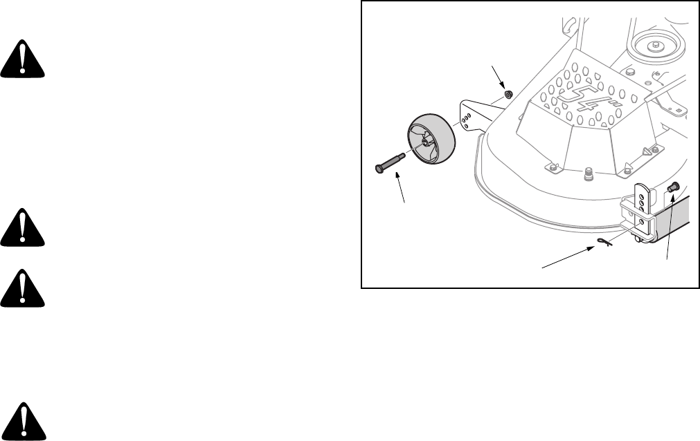
Figure 3
b. Remove the lock nuts and shoulder screws
which secure the front gauge wheels to the
deck.
c. Place the deck lift handle in the desired
mowing height setting.
d. Insert the shoulder screw with the gauge
wheel into the index hole that leaves
approximately 1/2" between the bottom of the
wheel and the pavement.
e. Note the position of the index hole used; then
install the other gauge wheel into the
corresponding index hole of the other gauge
wheel brackets.
• If the gauge wheels have excessive clearance with
the surface below, lower the wheels to the index
hole that provides the approximate 1/2" clearance
as described above.
Roller (Model GT2300)
To adjust the height of the rollers found on the rear of
the mowing deck upward or downward, proceed as
follows:
• Place the deck lift lever in the lowest position.
• Remove the clevis pins and hairpin clips from the
deck roller brackets on the left and right sides of the
cutting deck. See Figure 3.
• Position the deck roller brackets up or down
through the slots on the rear of the deck until
desired position is reached, then re-attach with the
clevis pins and hairpin clips just removed.
IMPORTANT:
Be certain that the left roller bracket and
the right roller bracket are set in the same position.
Refer to Leveling the Deck on page 19 of this manual for
more detailed instructions regarding various deck
adjustments.
Cotter Pin
Lock Nut
Shoulder Screw
Clevis Pin