


ASSEMBLY
Assembly Section 2-17
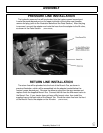
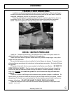
GENERAL HOSE INSTALLATION
Refer to the parts section for detailed information about hoses and fittings for this
application.
(ASM-C-0011)
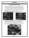
HOSE COVERING
Secure hoses together with zip ties wherever loose. Wrap the hoses between the
swivel and main boom with the hose cover provided. Wrap the hoses between the main
boom and secondary boom with the hose cover provided. Where hoses may contact the
frame or other edges, wrap with split hose and secure with hose clamps or zip ties.
On non cab units, the pressure and return hoses from the control valve will also need
to be routed inside the protective clear hose wrap. Cover the valve, valve fittings with the
yellow hose cover and secure with black string provided.
(ASM-C-0058)
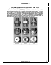
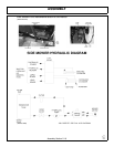
SOLENOID BRAKE VALVE
Install a solenoid valve on the mounting bracket with the supplied hardware as shown
in the Parts Section in this manual. While installing the fittings to the brake valve, the
electical coil on the spool may have to be removed to make room. When reinstalling the
coil, it is important to use no more than 5 ft. lbs. (or 60in. lbs.) torque. WARNING: OVER
TORQUE TO THE COIL WILL RESULT IN HYDRAULIC FAILURE OF SPOOL.
(ASM-C-
0025)
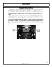
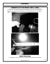
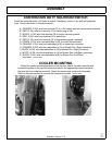
TEMPERATURE GAUGE MOUNTING (OPTIONAL)
Mount the temperature gauge where it is clearly visible to the operator. Attach the
green (-) wire from the negative post on the gauge to a grounded bolt on the tractor
frame. Remove paint if needed to make a good ground. Remove the pipe plug from the
side of the hydraulic reservoir and install the temperature sensor using thread sealing
tape. Run the white wire from the (s) sensor post of the gauge to the temperature sensor
on the hydraulic reservoir tank.
(ASM-C-0051)
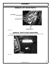
MAIN FRAME INSTALLATION
With an overhead hoist and / or jack-stands, raise one side of the frame up to the
correctly matching mounting holes. Install capscrews and all other hardware as shown in
main frame parts section to secure the sides of the main frame to the tractor casting, DO
NOT tighten at this time. Remove the capscrews one at a time and apply a thread locking
agent. Reinsert the capscrews and tighten / torque to values noted in the torque chart
located in the maintenance section of this manual.
(ASM-C-0003)
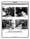
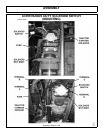
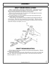
AXLE BRACE MOUNTING
Position the right axle brace under the tractor right hand side. Raise the brace up to
the matching mounting holes in the main fame and rear axle housing. Note the right side
brace is installed on outside edge of the main frame and the left side brace is installed on
the inside edge of the main frame. Pictures below show right side brace installation.
Install the clamp plate with capscrews, washers and nuts as shown in the main frame
parts section. Apply Loc-Tite to the threads and torque to the values noted in the torque