--9--
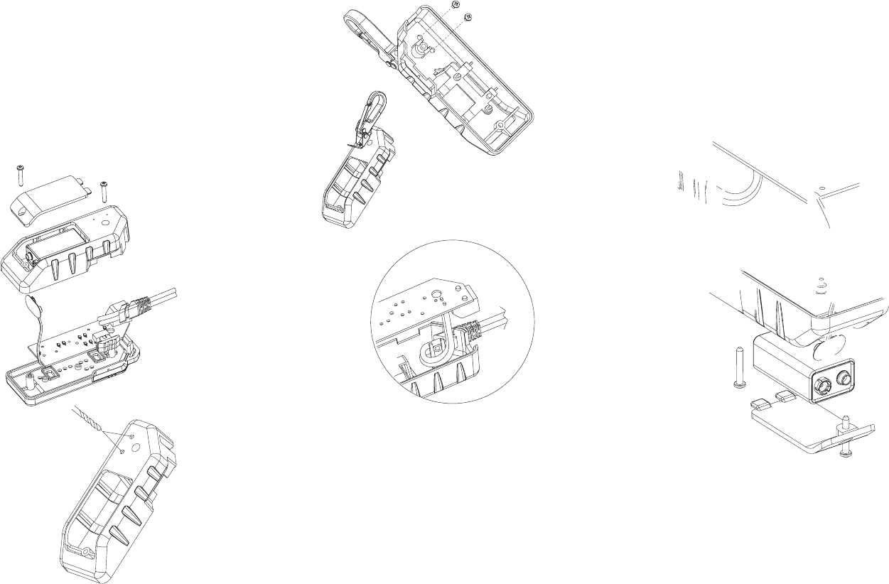
3) Place PCB
board onto
alignment
posts (2) in
bottom case.
Direct battery
terminal through
bottom case,
as shown.
4) Place buttons
(2) onto PCB
board; make
sure buttons
are positioned
flat on PCB board,
with alignment
posts inserted into
corresponding holes
in PCB board.
5) Place top case onto
the assembly.
6) Hold complete assembled
unit together firmly.
Turn unit over. Insert body
screw into top screw hole near
RJ connector and tighten.
7) Re-connect 9
V battery and insert into battery compartment.
8) Place battery door into position. Insert second body screw
into lower screw hole and tighten.
--8--
Step #3
1) Insert two (2)
#4-40-.250 screws
(supplied) into drilled
holes from inside of body.
2) Attach clip to body,
as shown.
Step #4 (Re-assembly)
1) Insert cable into slot
in bottom case
(see detail A).
2) Place slide switch
cover in side slot
(see detail B).
--7--
BATTERY REPLACEMENT
1) Remove screw on the rear of the Turbo Tone
™
with a #1
Phillips screwdriver and remove battery door.
2) Remove old battery and disconnect from battery leads.
3) Snap the battery leads onto a new battery (9V, alkaline).
Place battery in case.
4) Close tester and replace screw. Do not over tighten.
BELT CLIP INSTALLATION
(Belt clip sold separately)
Step #1
1) Remove two (2)
#4-.750 body
screws, as shown.
2) Remove battery
door and battery.
3) Lift off back cover
and remove cable
assem./strain relief
from slot in back case.
4) Separate back cover
from rest of unit.
Step #2
1) With back case removed from unit,
locate two (2) counter sink marks
on back side.
2) With .125 (1/8") dia. drill bit,
drill holes into back case at
both countersink marks.
3) Clean any burrs and debris
from inside of body.


