


Operation Teledyne API M751H High Performance Zero Air Generator
22 07773A DCN6833
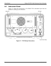
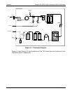
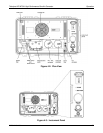
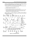
4.2 Components
This section describes the main components and their functions (not all components
are visible from the plan view).
4.2.1 Intake Filter
The intake filter is a serviceable assembly that houses a screen filter. Maintenance
instructions are provided in Section 5 of this manual.
4.2.2 Compressor
The compressor is a single-cylinder oscillating piston type driven by a split capacitor
AC motor. The compressor is dry; that is, there are no lubricants which can
contaminate the compressed air. The pistons are sealed by flexible TFE piston rings,
and after a short run-in period to seat the rings, should last for years. There are no
diaphragms.
The compressor is mounted on a sub-plate which is supported on four tuned vibration
isolators.
4.2.3 Cooling Coil
The cooling coil consists of several turns of copper tubing coiled through which the
cooling fan blows outside air.
4.2.4 Water Trap
The water trap is a coalescing type. Supersaturated air enters the trap and is rapidly
swirled causing the water droplets to deposit on a membrane where the drops
coalesce and gather in a puddle at the bottom of the filter bowl.
4.2.5 Water Drain Valve
The water drain valve is a stainless steel solenoid-operated valve through which
accumulated water is drained from the filter. The valve is sequenced by the controller
and is pulsed open every minute to remove water from the filter bowl.
CAUTION
THE WATER/AIR SPRAY LEAVING THE DRAIN FITTING SPURTS AT
A HIGH VELOCITY AND MUST BE CONDUCTED AWAY FROM ANY
SENSITIVE COMPONENTS.
The operation cycle has been preset at the factory and is not adjustable.