


10
English
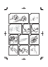
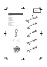
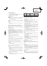
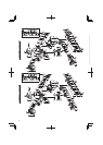
Insert the drive shaft into the clutch case of the engine properly until
the marked position (2) on the drive shaft tube meets the clutch
case.
Some models may come with the drive shaft already installed.
NOTE
When it is hard to insert drive shaft up to the marked position on
the drive shaft tube, turn drive shaft by the cutter mounting end
clockwise or counter-clockwise. Tighten tube locking bolt lining
up the hole in the shaft tube. Then tighten clamp bolt securely.
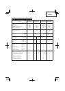
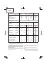
Model
TCG24EASP (SL)
TCG24EAS (SL)
TCG24EASP (S)
TCG24EAS (S)
TCG27EASP (SL)
TCG27EAS (SL)
TCG27EASP (S)
TCG27EAS (S)
Engine
Displacement (cm
3
) (ml)
Spark plug
Idling speed (min
-1
)
Recommended max. speed (min
-1
)
Speed of output shaft (min
-1
)
Max. engine output (kW)
23.9
NGK BMR7A
3000
11000
9900
0.85
23.9
NGK BMR7A
3000
11000
9900
0.85
26.9
NGK BMR7A
3000
11000
9900
0.9
26.9
NGK BMR7A
3000
11000
9900
0.9
Fuel tank capacity (cm
3
) (ml) 520
Dry weight (kg) 4.6 4.9 4.9 5.1
Cutting attachment Type / Dia. (mm) Nylon cord
Nylon
cord
Metal
blade /
230
Nylon cord
Nylon
cord
Metal
blade /
230
Sound pressure
level LpA
(dB (A))
(ISO11806)
Equivalent
Uncertainty
92
3
92
3
93
3
93
3
93
3
95
3
Measured sound
power level LwA
(dB (A))
Measured sound
power level LwA (dB (A))
Guaranteed sound
power level LwA (dB (A))
(ISO11806)
Equivalent
Uncertainty
(2000/14/EC)
Racing
(2000/14/EC)
Racing
105
3
108
111
105
3
108
111
105
3
108
111
107
3
110
111
107
3
110
111
107
3
110
111
Vibration level (m/s
2
) (ISO7916)
Equivalent (Front / Left handle)
Equivalent (Rear / Right handle)
Idling (Front / Left handle)
Idling (Rear / Right handle)
Racing (Front / Left handle)
Racing (Rear / Right handle)
6.2
5.8
4.2
3.1
7.7
7.6
3.7
4.7
2.6
4.4
4.6
5.0
8.5
6.5
2.6
4.4
11.6
8.2
6.2
7.4
3.1
2.0
8.3
10.4
4.8
4.0
2.8
3.9
6.2
4.1
8.6
6.1
2.8
3.9
11.9
7.6
NOTE
Equivalent noise level/vibration level are calculated as the time-weighted energy total for noise/vibration levels under various working
conditions with the following time distribution: 1/2 Idle, 1/2 racing.
* All data subject to change without notice.
ASSEMBLY PROCEDURES
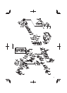
Drive shaft to engine (Fig. 1)
Loosen tube locking bolt (1) about ten turns so that the bolt point will
not obstruct drive shaft tube to be inserted. When inserting drive
shaft tube, hold the tube locking bolt outward preventing inside
fi tting from obstructing as well.