www.tanakapowerequipment.com 5 custsvc@tanaka-ism.com
Owner’s Manual
TLE-550
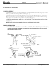
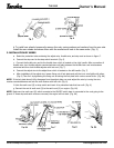
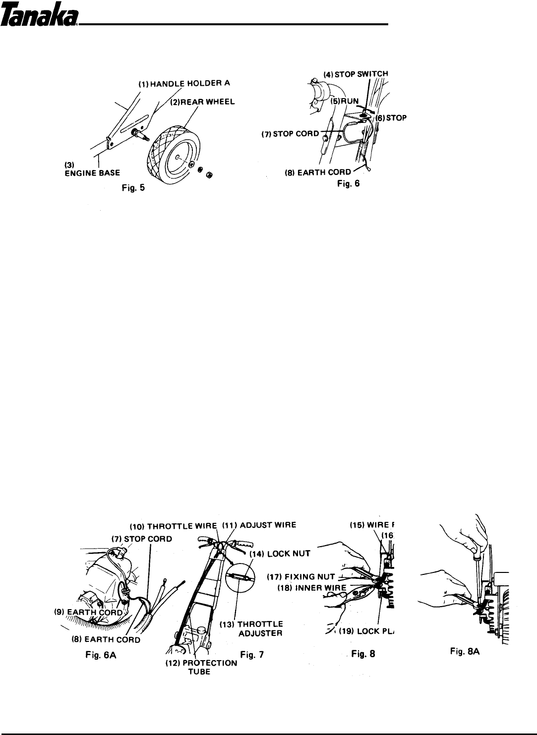
b. To install rear wheels, temporarily remove the nuts, spring washers and washers from the rear axle.
Install the rear wheels and secure them with the washers and nuts in the same order. (Fig. 5)
3. INSTALLATION OF WIRES
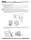
a. Route the protection tube containing the adjust wire, throttle wire, and stop cord as shown in figure 7.
b. Connect the stop cord to the stop switch terminal. (Fig. 6)
c. Connect the throttle wire end to the throttle lever which is located on the right handle. After connection of
throttle wire, turn throttle adjuster counterclockwise until play between the throttle lever and wire becomes
minimized and then lock throttle adjuster with lock nut. (Fig. 7)
d. Connect the adjust wire to the adjust lever which is located on the left handle. (Fig. 7)
e. After installation of the adjust wire, loosen fixing nut of lock plate and pull the inner wire lightly with pliers.
(Fig. 8) Then fix it by tightening the fixing nut as locking the lock plate with a minus screw driver. (Fig. 8A)
NOTE: If the lock plate doesn't fully disengage from the adjust plate you must adjust the wire by turning the wire
receiver counterclockwise and lock the wire receiver with lock nut. (Fig. 8)
f. Untie the earth cord (8) on stop switch and insert it to protection tube that has a slit. (Fig. 6)
g. Connect the end of earth cord (8) to the earth cord (9) on engine. (Fig. 6A)
NOTE: Make sure the earth cord (8) which connects to the ON/OFF switch base is connected to the cord going to the
ground. If these stop and earth wires are reversed, the engine will not start. (Fig. 6A)


