


www.tanakapowerequipment.com 5 custsvc@tanaka-ism.com
Owner’s Manual
AST-210,AST-5000
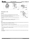
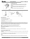
NOTE!
When it is hard to insert drive shaft up to the marked position on the drive shaft tube, turn drive shaft by the cutter
mounting end clockwise or counterclockwise. Tighten tube locking bolt lining up the hole in the shaft tube.
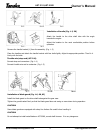
Drive shaft to engine (AST-210)(Fig. 1-1D)
Loosen tube locking bolt (1).
Insert the drive shaft into the clutch case of the engine properly until the marked position (2) on the drive shaft tube
meets the clutch case.
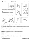
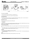
Throttle control (Fig. 1 -1 B, 1C)
• Remove throttle trigger screw (1) and slide the throttle trigger assembly away from the shaft grip temporarily. Connect
the throttle wire in the hole of the throttle trigger.
• Locate throttle trigger in its original position by squeezing the trigger, then slide the throttle trigger assembly back
against the shaft grip then install and tighten the throttle trigger screw (1).
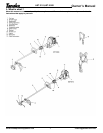
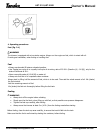
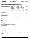
3. Assembly procedures
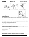
Drive shaft to engine (Fig.1-1)
• Apply a small amount of oil or grease to insert part of shaft tube, loosen shaft tightening bolt (1) and remove location
bolts (4).
• Insert the throttle wire (3) through the hole of the shaft grip and connect the electrical coupling (2).
• Pull flexible inner shaft out of shaft tube about 3 " and insert it into the square hole in the clutch shaft.
Insert the shaft tube into the rubber damper on the clutch case until the location hole lines up on the shaft tube (5) and
on the clutch case. If it will not go in far enough ' turn the shaft at the gear case end until the shaft tube drops into place.
*install location bolts, tighten location bolts and shaft tightening bolt.