


OPERATING YOUR NEW CUTTER
CAUTION:
TRAGIC ACCIDENTS CAN OCCUR IF THE OPERATOR IS NOT ALERT TO THE PRESENCE OF
CHILDREN. CHILDREN ARE OFTEN ATTRACTED TO THE MACHINE AND THE MOWING
ACTIVITY. NEVER ASSUME THAT CHILDREN WILL REMAIN WHERE YOU LAST SAW THEM.
The operation of any mower can result in foreign objects being thrown into the eyes,
which can result in severe eye damage. Always wear safety glasses or eye shields
before starting your mower and while mowing. We recommend wide vision safety mask
for over the spectacles or standard safety glasses.
STOPPING
• Move blade clutch lever to disengaged (vertical) position.
• Turn key switch to OFF position.
TOW HITCH OFFSET FEATURE
This trail mower has been designed to run offset from the
center of the tow vehicle in order to make the unit more
flexible in a wide range of mowing situations.
• The adjustable tow hitch of this mower can be assembled
from straight behind the tow vehicle to approximately 20”
offset to either side
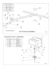
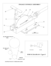
TOW HITCH OFFSET ASSEMBLY (refer to fig. 1)
• Install hitch tube (2) over the front torsion bar (1) on
mower (Note: the hitch tube can be placed anywhere
along the length of the torsion bar). Secure the hitch tube
in place using four 3/8-16 x 2 ½ bolts (4) and 3/8 -16
nyloc nuts (5).
• Install the “L” hitch (3) into the hitch tube, and loosely
secure with two 5/16-18 x 2 12 bolts (6) and 5/16-18
nyloc nuts (7). The “L” hitch will be secured in place
after the front to back adjustment has been determined
(see next step).
FRONT TO BACK ADJUSTMENT
To obtain the best cutting results, the mower deck should be
adjusted so that it is parallel to the ground. To check front to
back adjustment, measure from the bottom edge of the deck to
the ground at both the front and rear of the deck. This next
series of instructions is best done with the mower and tow
vehicle together.
• Install the hitch swivel (8) to the tow bar of the tow
vehicle. (refer to fig. 1)
• Raise the hitch tube of the mower until the bottom of the
deck is parallel to the ground. Note the position of the
clevis on the “L” hitch in relation to the hitch swivel on
the tow vehicle. The “L” hitch will have to be moved up
or down to match this height.
• Set the mower back on the ground, remove the hardware,
slide the “L” hitch into the predetermined position, and
reinstall the nuts and bolts. The hardware can now be
tightened.
ATTACHING CUTTER TO TOW VEHICLE
• Place cutter behind tow vehicle and back up to it for
attaching.
• Slide tow bar of cutter over the tow vehicles hitch so that
holes line up.
• Insert hitch pin until it extends through the bottom of the
tow bar.
• Place safety latch over the end of the hitch pin.
• Secure control console to tow vehicle, making sure it can
be reached from the operating position (see pre-assembly
instructions. Use provided Velcro straps to secure control
cable to cutter frame, hitch, and tractor.
Important: Make sure control cable is unrestrained
through the turning range of the tow vehicle.
TRANSPORTING YOUR CUTTER
• Disengage the blade.
• Shut off cutter engine.
• Place cutter deck in the highest position.
CAUTION:
SHUT OFF MOWER ENGINE AND REMOVE
SPARK PLUG WIRE FROM SPARK PLUG
BEFORE MAKING ANY ADJUSTMENTS TO
THE MOWER.
CUTTER HEIGHT ADJUSTMENT
The cutting height range of this unit is from approximately 2
1/2 to 6 inches. Heights are measured from the ground to the
blade tip with the engine not running. Rotate height
adjustment crank handle in a clockwise direction to raise the
cutter and in a counter clockwise direction to lower.
BEFORE STARTING ENGINE
• Fill engine with oil (see engine manual for proper
procedure and requirements).
• Add gasoline. Fill fuel tank using fresh clean unleaded
gas.